MuckOff: a rear bicycle-mudguard
Requirement
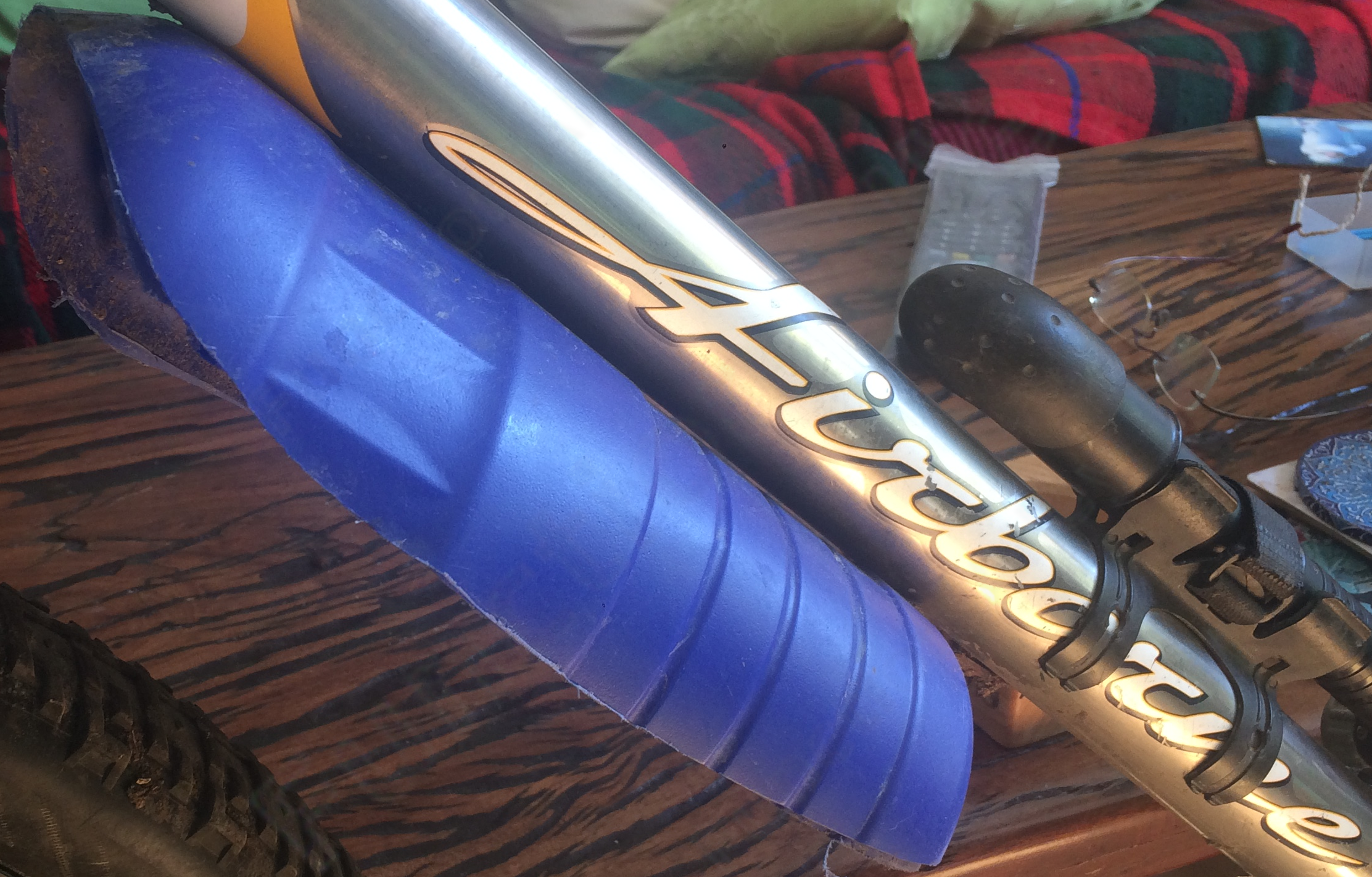
I hate bicycle-mudguards; they flap, rattle & flop like a bowl of Rice Krispies, & consequently ruin an otherwise near-perfect machine. OK, perhaps "hate" was too strong, but I'd definitely go as far as mild irritation. For me, it has always been a question of whether I was irritated more by the mudguard or the mud … oh hold on, I'm probably more irritated by trends in the bike-industry.
This project is solely about the rear mudguard, since for years, I've used an (empty) bleach-bottle for the front one (it's not very good, but it is cheap). Bisect it vertically into near symmetrical halves, bolt one half onto the underside of the down-tube (where my bike-frame has two threaded holes), then trim the leading edge to prevent collision with the front tyre when the suspension-forks are fully compressed.
Naturally I've already decided to build my own, it only remains to fabricate plausible justification for that decision.
Issues:
-
To invert the bike (perhaps to facilitate wheel-removal), I deprecate leaning over the top-tube & flipping the bike sideways (which invites lumbar vertebrae popping like tight waistcoat-buttons & an extended period in traction) & prefer to flip the bike longitudinally by flicking the rear wheel under the bike … but the rear mudguard stabs into the ground, or if you're really lucky, your foot.
-
After removing the wheels to put the bike in a bike-bag, once again the mudguard protrudes like a sore thumb.
-
One can typically swivel the rear mudguard around the vertical axis of the seat-post, so that it points towards the handlebars, thus avoiding the above problems. This is only possible because the manufacturer of this blighted product could find no other attachment-point on which to rely; the only other thing they might assume is that there may be threaded holes in your frame to support a mudguard or pannier-rack. The bike-frame's geometry & size, the wheel's radius & width, & whether the bike has rear suspension, are unknown to them. Regrettably, attachment to just the seat-post also leads to the mudguard accidentally swivelling around this single attachment-point, away from alignment with the rear tyre, when in use.
-
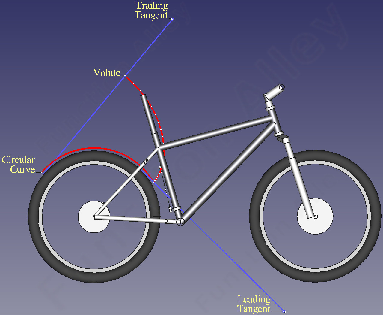
The profile of mudguards is another irritation. Traditionally mudguards follow the circular outer radius of the tyre, which seems sensible, but after realising that mud doesn't fling from the tyre radially, but rather tangentially, it's clearly sub-optimal. The trailing edge of a rear mudguard designed in this fashion, would be parallel to the rays of mud emerging from the rear wheel, & therefore ineffective. If the mudguard were always perpendicular to the tangents from the tyre, a volute would result. Whilst mathematically pleasing, the volute takes excessive space (& it's hard to model). Fortunately, only the ends of the curve need to be perpendicular to the rays of mud emerging from the tyre, between which the curve is free to follow the shortest path which avoids both the frame & the tyre.
Bad Ideas in Mountain-bike Design: rant, rant, rant …
-
1× drive-trains:
-
- Pros:
-
-
They're lighter.
-
The gear-ratios are geometrically spaced.
-
It's easier to work-out how to change to the required ratio.
-
- Cons:
-
-
The chain has to bend sideways by up to ≈half the width of the wider cassette, leading to friction & wear.
-
The chain has to be thinner & is therefore stretchier.
-
The range of ratios spanned is shorter than 3× drive-trains, typically resulting in a higher lowest ratio.
The cassette's lowest-ratio cog now has a radius comparable to a dinner-plate & the cassette is correspondingly expensive.
The dérailleur has to be capable of spanning the wide range of cog-radii.
-
The rear wheel has to be dished more to accommodate the wider cassette making it weaker.
-
-
Low-normal (AKA "Rapid Rise") rear dérailleurs:
-
This technology allows one to proceed rapidly to the highest gear, exactly what you do not want when you unexpectedly encounter a steep incline .
It also requires compatible gear-shifters.
-
29" wheels:
-
Whilst you might be swayed by the apparent preference of professional cyclists for this wheel-diameter … they ride what their sponsors tell them to.
-
Pros:
-
-
Rolling-resistance:
-
Rolling-resistance is inversely proportional to radius … but it also reduces with tyre-width & tyre-pressure.
CAVEAT: this advantage is offset (depending on speed) by the increased aerodynamic drag.
-
Roll-over Ability:
-
The larger radius bridges bumps better, so the ride is smoother.
CAVEAT: there's less room for suspension-travel.
-
Stability:
-
Bumps & dips cause the bike to pitch less because of the longer wheel-base.
CAVEAT: correlation doesn't imply causation; a longer wheel-base doesn't require a larger wheel-radius & can if desired, be achieved with smaller wheels.
CAVEAT: see manoeuvrability.
-
-
Cons:
-
-
Weaker:
-
The wheels are less resistant to transverse forces due to the narrower angle of the spokes as they converge from the axle to the rim.
-
Higher mass for the:
-
-
wheels.
-
tyres.
-
forks.
-
disk-brakes, which now have to work through a longer lever-arm.
-
spokes, which have to transmit the higher required braking-force & combat the weaker resistance to transverse loads.
The effect of this depends on the incline.
-
-
Higher angular inertia:
-
So the kinetic energy required to spin the wheels up to a given bike-speed is proportional to their mass. Which means times slower acceleration, & to maintain the same deceleration, larger brake-rotors & spokes.
-
Reduced compatibility:
-
26" wheels were a good compromise, because people within the a few standard-deviations of the average height, could ride bikes with this wheel-diameter. Now, if you're riding with your partner, you have to carry a second spare inner-tube.
-
Manoeuvrability:
-
The wheel-base is typically longer, so the turning-circle is proportionally wider.
See stability.
-
-
-
Post-mount disk-brakes:
-
The preceding (I.S.) mounts had the thread either in an adapter (or in the brake) rather than in the fork or the frame, making it a lot cheaper to repair if it strips … & what was the motivation to change ?!
-
Electric motors:
-
-
I kept my last bike for 45 years, after which it wasn't taken to a scrap-yard, but rather sold, because it still worked … & it wasn't even new when I bought it ! The battery in an e-bike will last no longer than any other Li-ion battery, but the manufacturer probably won't want to know you after ≈10 years. There doesn't currently seem to be much standardisation of the battery (geometry, voltage, connector), so third-party solutions will be thin on the ground.
-
They're ≈double the weight of a traditional bike. That matters:
-
after the motor cuts-out because you just tried to exceed the legally restricted speed.
-
you have to push it (e.g. up steps).
-
when it falls on top of you.
-
-
You should probably avoid charging them indoors, & that matters when you're touring & your accommodation's insurance doesn't even permit this.
-
-
Internal cable-routing:
-
-
Aerodynamics:
-
This idea has validity in track-racing where aerodynamics is critical, but on a mountain-bike … really ?
-
Maintenance:
-
Sure the bike now looks sleek, but these cables & hydraulic hoses are routed through handlebars, head-posts, down-tubes etc., so changing either the former or the latter is going to test your patience. If a hydraulic hose needs to be disconnected, the brake will have to be bled & the hose may need to be replaced.
-
Functionality:
-
The routing is through tight angles, so cables probably won't pull freely. Hydraulic hoses routed through tight angles may kink & wear, & worse, you can't even see this train-wreck approaching.
-
Proprietary:
-
The cable-routing system is typically proprietary … great, more technical obsolescence.
-
Many of these changes are merely the industry's attempt to get you to throw up your arms in horror @ the labyrinth of incompatible parts & buy a new bike.
Design-criteria
-
I should be able to collapse the mudguard so that the bike can be inverted & stowed.
-
Construct a folding mudguard, using the same principle as stringing tent-pole segments together with shock-cord.
-
It must be stiff enough (when the mountain-bike bounces over boulders) to prevent it vibrating; vertically & hitting the rear wheel; sideways (possibly combined with twisting), allowing mud to flick past it.
-
Make the mudguard tubular, thus increasing its stiffness to bending & twisting.
-
The design will probably be largely 3D-printed, so it must fit inside the volume of the 3D-printer.
-
Use the criterion that the mudguard should be foldable, to subdivide it into sections connected by shock-cord. CAVEAT: to prevent the shock-cord rattling against the interior walls of the tube, it must be laterally constrained.
-
Ideally the mudguard would be water-resistant. Shock-cord is typically unaffected by water, but water in the tubular structure would increase its weight. This is of greater significance with hygroscopic materials, since absorption might distort the part.
-
-
Seal the tube-ends.
-
Orientate the tube-junctions to expel any water which manages to intrude, rather than funnelling it inwards.
-
Make the underside smooth, to shed mud & water quickly (it also facilitates one in cleaning mud off). N.B.: were the cross-section merely an open semi-circle rather than a closed tube, then stiffening ribs would probably be required on the underside, to which mud would cling (as it does with my ersatz front mudguard).
-
Minimise external features to reduce the surface-area through which moisture can be absorbed.
-
-
The mudguard should shield the angular range from the rider's back through to the front dérailleur-actuator (Yes, I still have one … because it's better). Since there's a restricted space between the seat-tube & the rear wheel, there's a limit to how close one can extend the leading end of the mudguard down towards the front dérailleur-actuator. So, I estimate that it'll need to shield ≈110°. N.B.: since the trailing tangent is perpendicular to the leading tangent, the angle the mudguard must span is only ≈20°.
-
In order that the mudguard actually shields mud throughout its angular span, it must skim the tyre @ the leading edge, which can be achieved using a flexible mud-flap.
To minimise material & weight, the leading edge of the mudguard will be radial & the trailing edge tangential, to the outer surface of the tyre, following the shortest path between.
Modelling
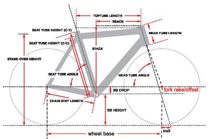
Before launching headlong into any design, I've found it invaluable to model the environment in which a new product must operate, in this case, the bike. The task of accurately measuring a bike-frame should not be underestimated. I couldn't measure any angles without buying a special gauge, & measuring tube-lengths leads one to question exactly where within a junction, each tube terminates. I could measure tube-diameters accurately with callipers, so the trick was to extend a tape-measure along the length a tube, wrap round the tube to which it butts & back along the other side, to find . CAVEAT: this calculation assumes that the tube to which it butts is perpendicular. Some considerable thought needs to be applied to the:
-
chain-stays, which are splayed outwards from the bottom-bracket to the rear axle, rise gently from the low-point of the bottom-bracket, & may also be curved.
-
seat-stays which are splayed outwards to the rear axle, but @ an angle which changes after the seat-stay passes the top edge of the rear tyre.
-
head-tube angle, which is extremely sensitive to the measured lengths of the top & down tubes.
Once all the lengths are defined, the angles can be derived. This model then forms the environment for the CAD of the mudguard.
Implementation
FFF
Initially I tried to use FFF, since brokers (such as Craftcloud), provide access to many printer-owners willing to cheaply fabricate such a product. Regrettably this printing-process can cope with neither unsupported cantilevers nor the bridging of long gaps, consequently constraining one to printing tubular structures with a vertically orientated axis … not ideal.
-
The tall thin structures will require buttressing to prevent them rocking during printing (especially on a bed-slinger).
-
The mechanical properties of parts printed with this process are anisotropic, regrettably expose the weak build-plane to the stress induced by bending the mudguard.
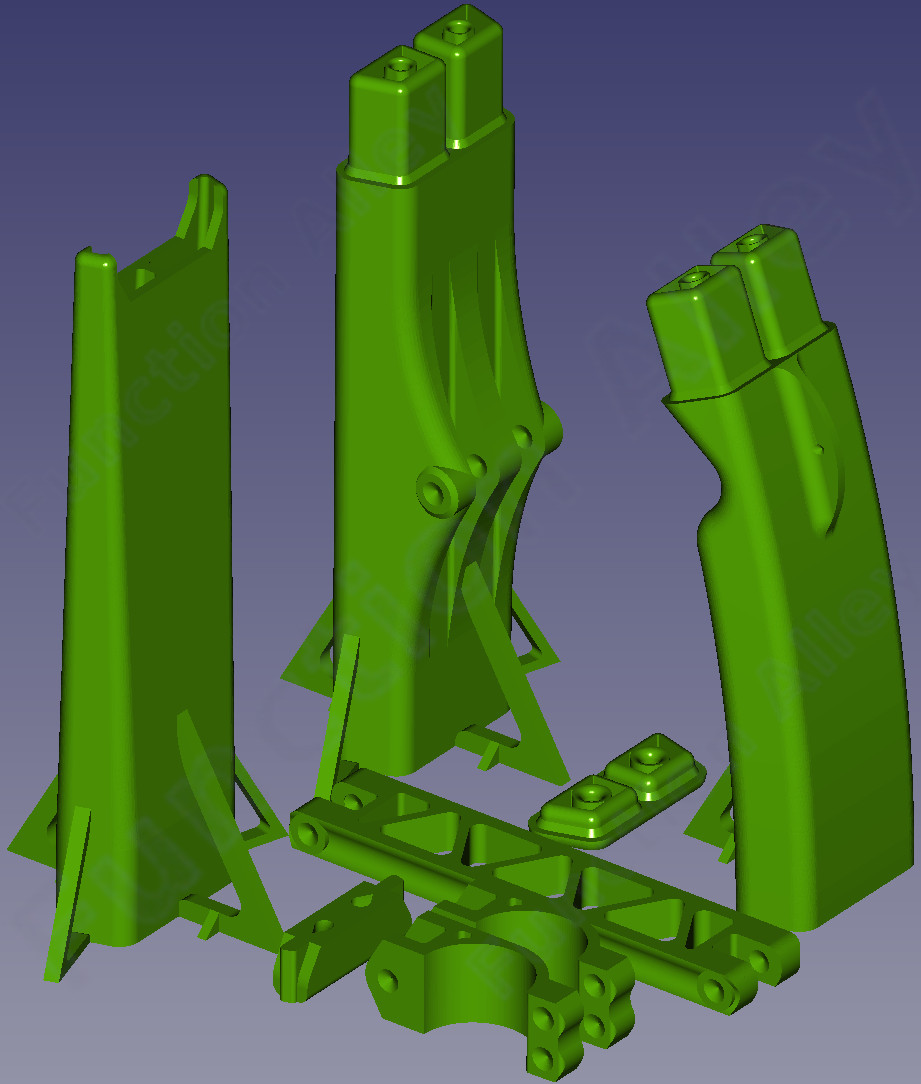
Without evidence that these issues are insurmountable, I proceeded to design the mudguard for printing with FFF. The structure was partitioned mainly into three equal length tubular parts.
-
A leading curved tube includes a notch on the underside, where it wraps over the short transverse tube between the seat-stays. CAVEAT: it is perhaps fortunate that my bike-frame has a space between the seat-stays which matches the width of the tyre (although there's an obvious reason for it to be similar). Some bike-frames have no gap here at all; the seat-stays join just above the rear wheel, into a single tube before connecting to the seat-tube.
The weakness this notch introduces, is offset by a crest on the top side.
-
A central tube with a mounting-point for connection (via a truss) to the seat-post. The mounting-point is located @ the middle of this central tube, from which the truss can extend perpendicularly to the seat-post, thus minimising the tensile loading of the truss.
-
The trailing tube is tapered to reduce mass & consequently vibration; the leading tube would also have been tapered if the resulting geometry had been tractable.
Each of these tubes has a 25 mm long plug @ one end & a socket @ the other, so that tubes may be connected to each other. In order to shed any water outwards, the plug points upwards from the lower tube into the upper tube.
Since the trapezoidal (matching the triangular gap in the frame) cross-section of the tubes is much wider horizontally (54.5 mm) than it is tall vertically (20 mm), each has a central vertical partition extending along its length, to reduce the tendency to buckle under a bending-moment.
There were several ancillary parts:
-
Tube-ends, which:
- @ the leading edge of the mudguard, both ends of the shock-cord terminate. CAVEAT: the shock-cord simply emerges from the tube-end through two holes, which compromises both water-proofing & looks, but the limitations of FFF constrained the design.
- @ the trailing edge of the mudguard, the shock-cord is internally doubled-back.
-
A truss which extends perpendicularly from the central tube to the seat-post.
-
A two-part seat-post clamp which connects to the truss.
This printing-process permits walls as thin as 1 mm, but I've chosen thicker tube-walls of 2.5 mm, which accommodates ≈4 filaments. This dimension isn't proportional to failure-resistance, since the mudguard vibrates because of its mass, & therefore a lighter structure would have reduced vibration-induced load & require less strength, but a thicker wall does make the part more resistant to being pounded with grit.
Each tube was orientated vertically for printing & was buttressed to limit rocking during manufacture.
CAVEAT: the buttresses were hard to subsequently remove cleanly.
Note that bolt-holes (universally M4) are not included in the design because they're rather large for this printing-process. The best I could reliably achieve was to leave pilot-holes for subsequent reaming.
Though PLA is cheap & has a relatively high tensile strength, it's brittle, so I chose ABS for its reputed toughness. I chose black because other colours of ABS are harder to print (which suggests that there may be strength-implications).
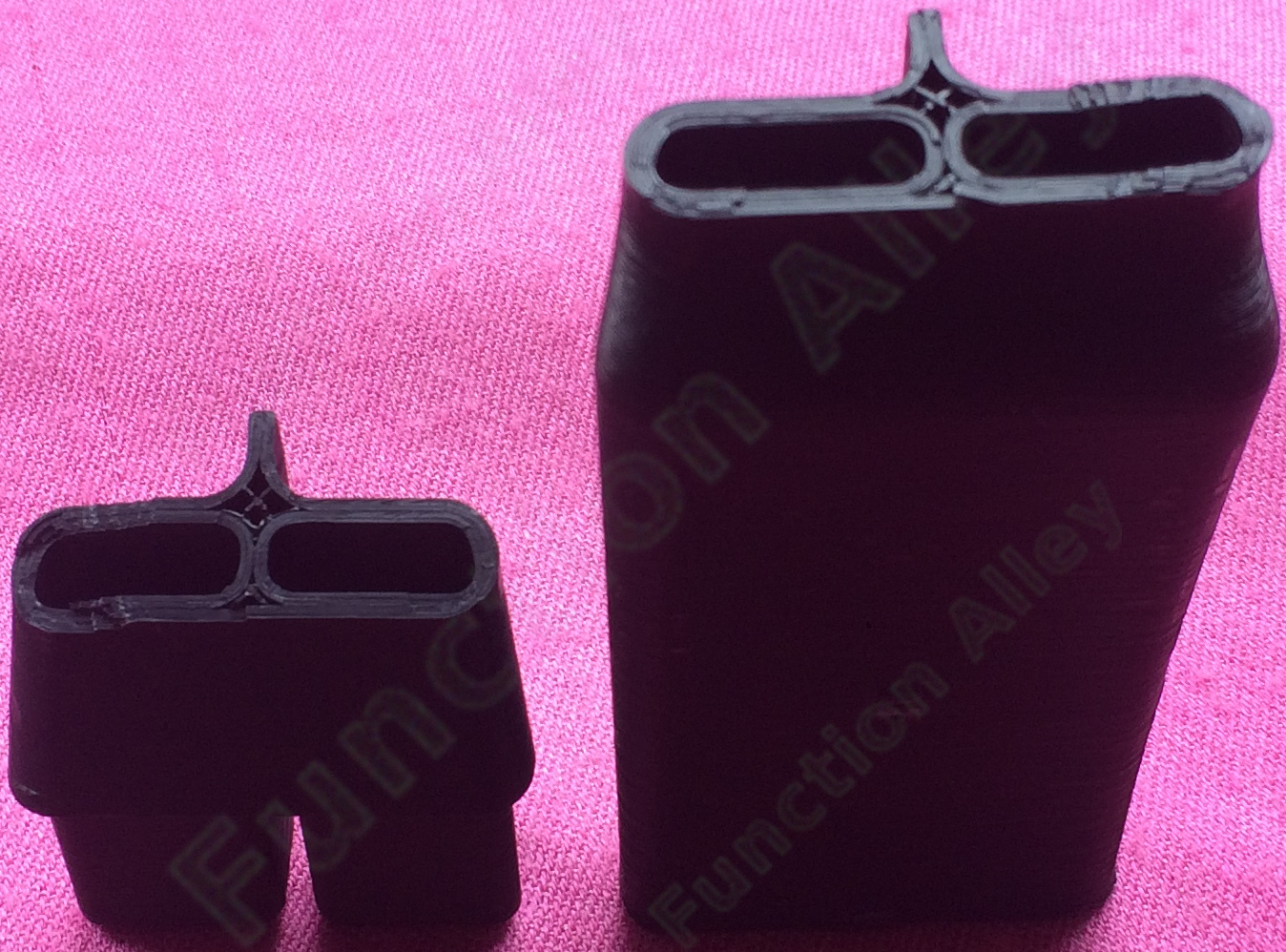
Strength
Though the parts were accurately printed & connected as required, I had little confidence in their strength, so I load-tested two connected tubular sections. I clamped one end of this assembly to a bench, & progressively increasing the weight hung from the free end of the resulting cantilever, until failure. Failure didn't occur @ the junction between the two tubes as I expected, but @ the notch in the leading curved tube (required to wrap over the short transverse tube between the bike's seat-stays). The bending-moment @ failure was cleanly across the weak build-plane. CAVEAT: this experiment also revealed that the part wasn't 100% infilled as had been requested of the manufacturer.

Annealing
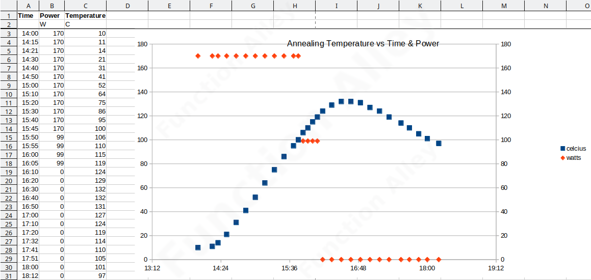
To fuse the weak build-planes & reduce the gaps between filaments, I attempted to anneal the parts
(a process which requires 100% infill).
I filled a slow-cooker with 0.1 - 0.7 mm quartz sand. Embedded a sample part in the sand, pushed in a thermocouple & packed the sand down (perhaps insufficiently). I then raised the temperature over a period of 2 h to the glass-transition temperature for ABS (≈105 C), before slowly cooling it.
The result was disastrous.
Annealing causes the part to shrink as the gaps between filaments are filled,
but it only does this perpendicular to the filaments, resulting in distortion.
Even without the distortion, for mating surfaces to remain compatible, they would each have to be printed in the same orientation.
The sand packed around the parts was intended to inhibit distortion, so it may be that a finer sand or more pressure was required. N.B.: this remedial process may be viable for a part which has unidirectional filaments & which hasn't any critical dimensions … but I'm going to have to be very bored before I bother repeat it.
To improve the strength I could:
-
Use another 3D-printing process which produces isotropic parts; SLA, SLS or MJF. The latter two processes additionally liberate the design of the part, from the constraint that cantilevers must be supported.
-
Split each mudguard-tube along its length, then fabricate these halves horizontally before bonding them back together.
SLS
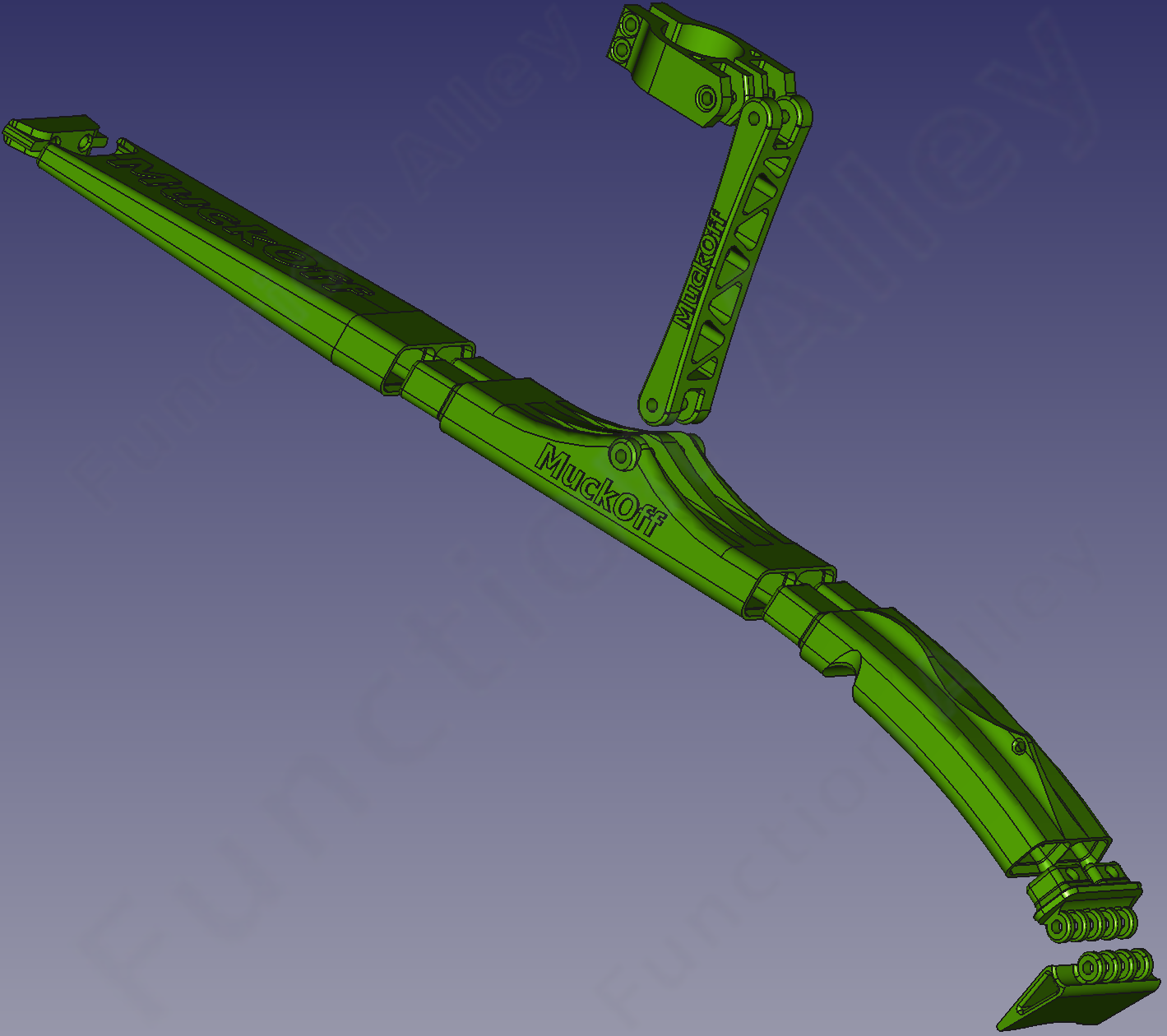
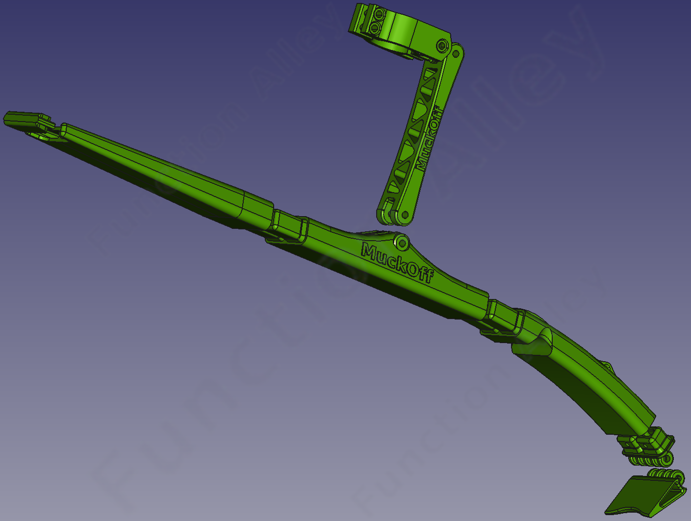
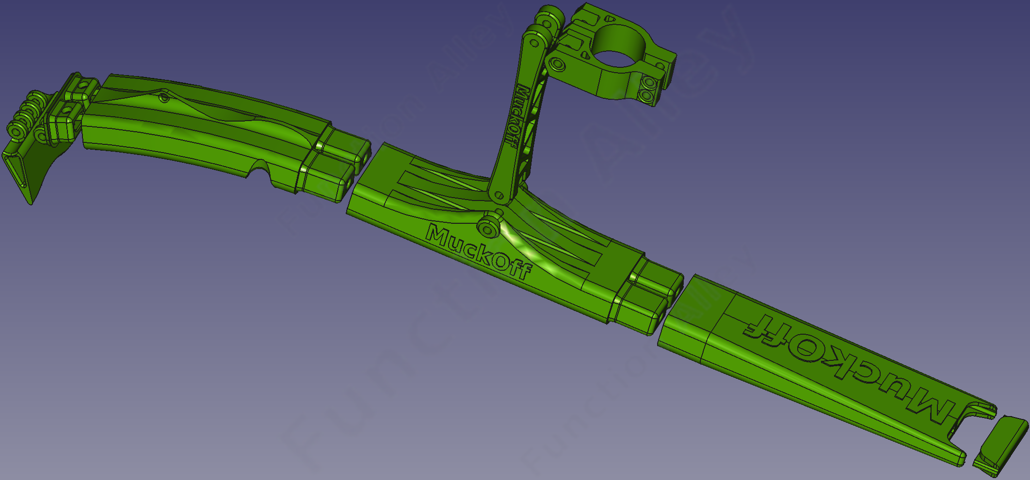
To simultaneously eliminate, the design-constraints imposed by FFF & the anisotropy, I decided to switch to SLS. This is a more industrial process & often considerably more expensive (but less so since the patent on this technology expired in 2014).
Since the FFF-compatible design assumed 100% infill, it's already suitable for fabrication by SLS, but simplification & improvements can be made.
-
The leading tube-end, where both ends of the shock-cord terminate, now entirely encloses the cord & more effectively seals the tube.
-
Since the mudguard is radially offset from the tyre, mud can emerge from the under its leading edge, so I added a hinged mud-flap to the leading tube-end, to shield the front dérailleur-actuator from mud. The hinge is composed of multiple interleaved lugs to generate sufficient friction to hold it in place, despite low torque on the hinge's bolt.
-
I added a second crest on the top surface of the leading curved tube, by which to secure a cable-tie to the seat-tube, if required.
-
The M4 bolt-holes were merely piloted in the FFF-compatible design, but these proved hard to ream without cracking the part along the build-plane (I cracked the truss). So for the SLS-compatible design, the bolt-holes were included.
-
The plug-connector formed on each tube-end, is now tapered into a hole just sufficient for the shock-cord, thus laterally constraining the cord & preventing it from rattling.
-
Buttresses were no longer required to stabilise the tall parts during printing, & were therefore removed.
-
I changed to using a stronger material, Nylon PA-12. This material also has good resistance to UV radiation. CAVEAT: colouration is now a more expensive post-processing (painting or dying) operation.
-
This printing-process permits walls as thin as 0.6 mm, but the previous wall-thickness was retained. The resulting mass of the Nylon is 253 g, which rises to 300 g when shock-cord & fasteners are added, so this may need to be revisited.
The wall-thickness @ the previously observed fracture-point was increased locally.
The central vertical strengthening partition, extending along the length of each tube, was honed into a truss to reduce weight & therefore vibration.
-
I added a frivolous brand-name to the uncluttered flat surfaces of some of the parts. It's not as though there's any intention to market this product, but I naïvely thought it looked cooler.
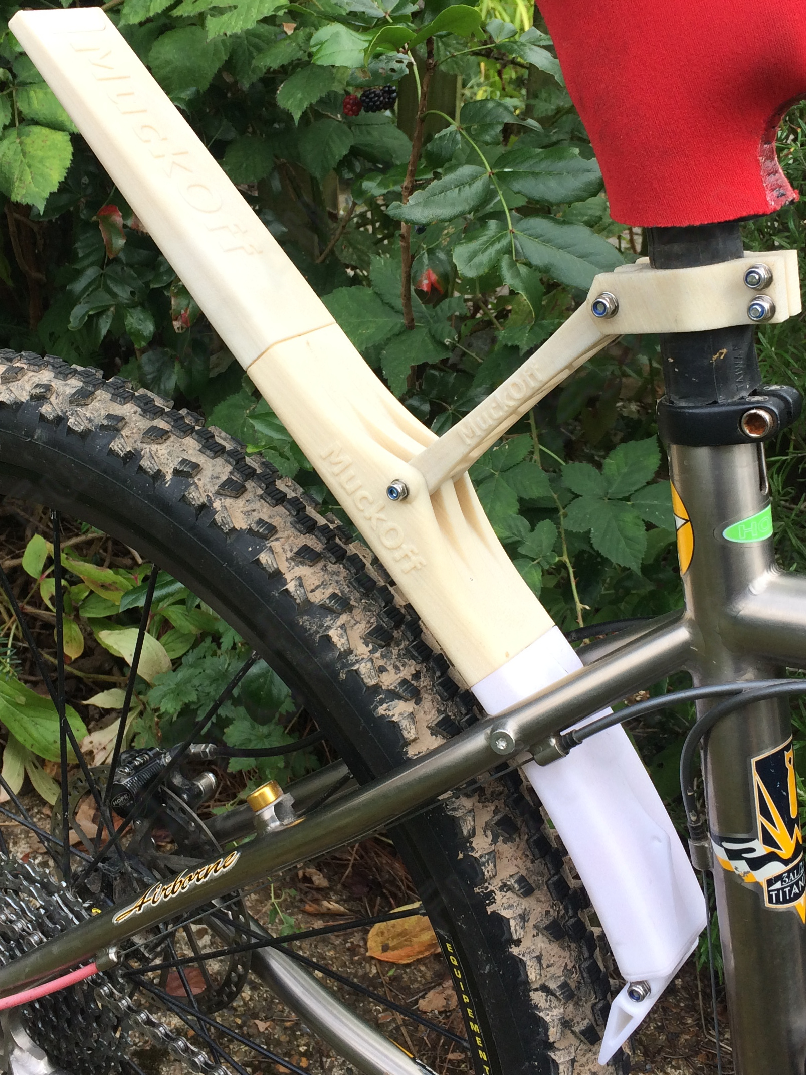
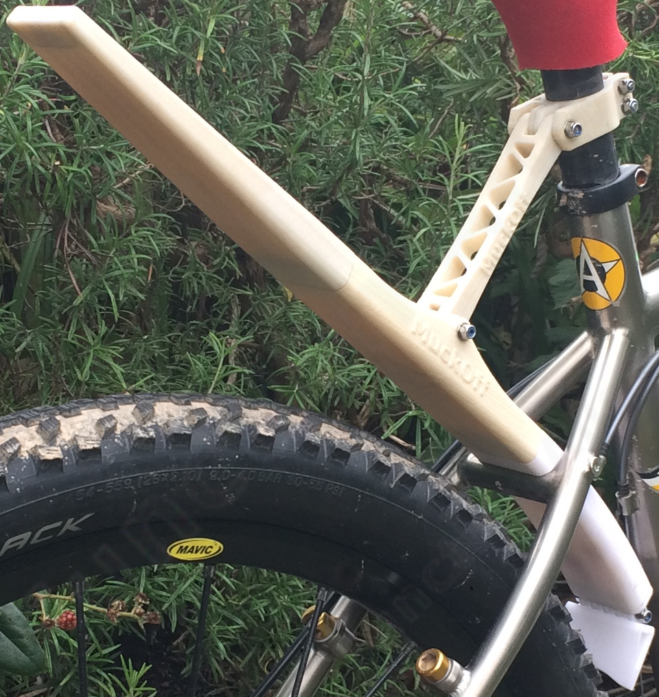
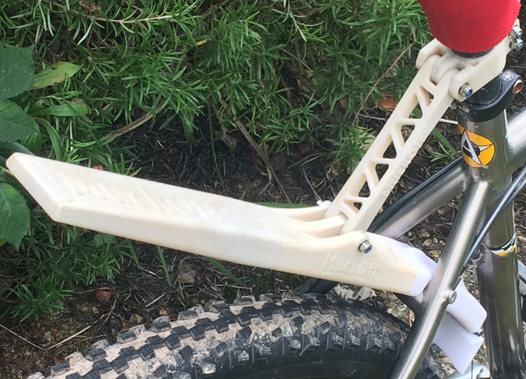
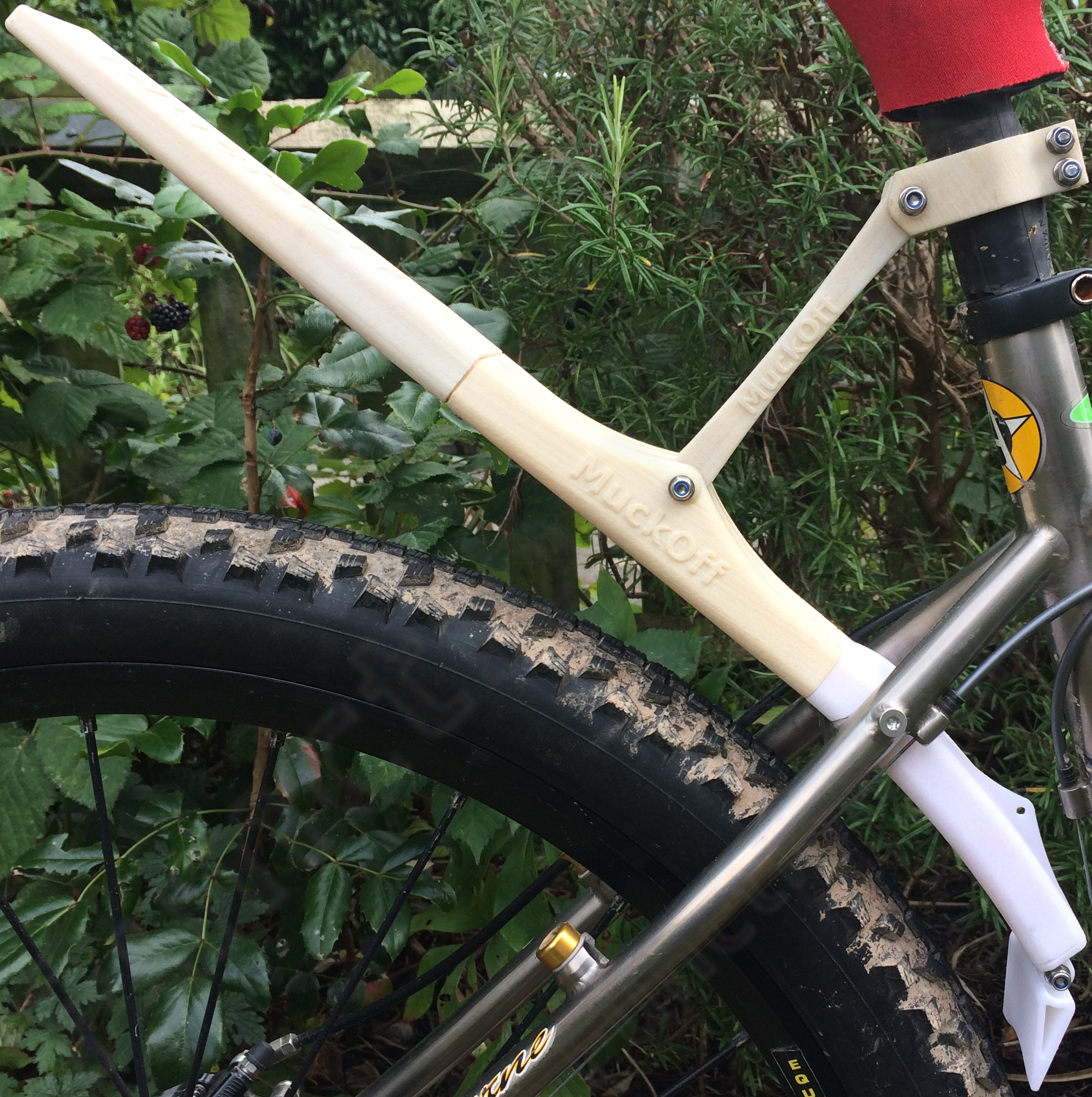
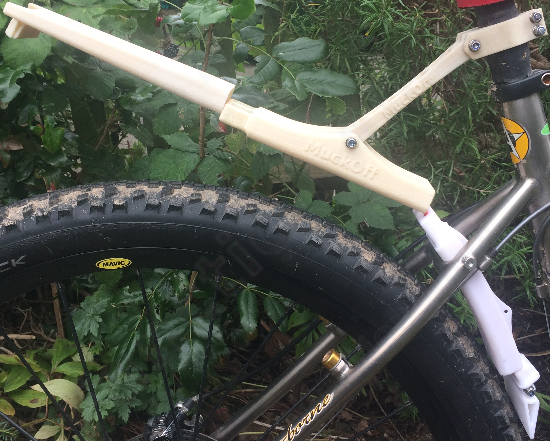
CAVEAT: I failed to account for the difficulty of manoeuvring the part into place. The part has the correct dimensions if it could be threaded into the triangular gap between the seat-stays, but @ the critical point where the leading curved tube of the mudguard bridges the transverse frame-tube between the seat-stays, it must be twisted axially (until one side is approximately perpendicular to the splayed seat-stays) before it can be inserted, & then twisted back to the working horizontal orientation … which it wouldn't. The third attempt includes a parabolic fillet to facilitate this process (for the printing of which I switched manufacturer & possibly therefore the brand of PA-12, hence the lighter shade of the revised parts).
Fasteners
All fasteners are M4, so only one tool is required, & stainless-steel to limit corrosion. Steel cap-head hexalobular bolts were used, & though relatively heavy, Nylon bolts of the required dimensions are difficult to find. Flat washers are used to spread the load @ each interface with Nylon. Nylon-insert lock-nuts were used since the bolts are only tightened to ≈1 Nm.
4 mm shock-cord was used, which is looped around a semi-circular canal within the trailing tube-end, so that both ends terminate inside the leading tube-end. Each end of the shock-cord has a small loop tied in it, which pushes into the leading tube-end where it is secured by an M3 bolt. The act of inserting the leading tube-end into the leading curved tubular section prevents this bolt from escaping; so neither a threaded insert nor nut is required.
An additional crest on the leading curved tubular section supports the possibility of a cable-tie between the mudguard & the seat-tube. This was a precaution in case it rattled, but hasn't been required.
N.B.: if necessary, one can wrap sticky tape around the plugs between tubular sections, to achieve a tight fit with the mating socket.
Road-test
The weather was regrettably good, but there were still puddles on the ground from two days earlier. I didn't want hammering rain, since I wanted mud to stick, revealing where the mudguard provided effective cover.
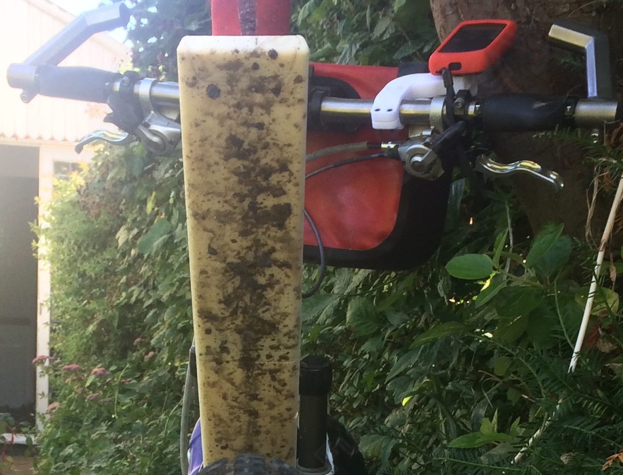
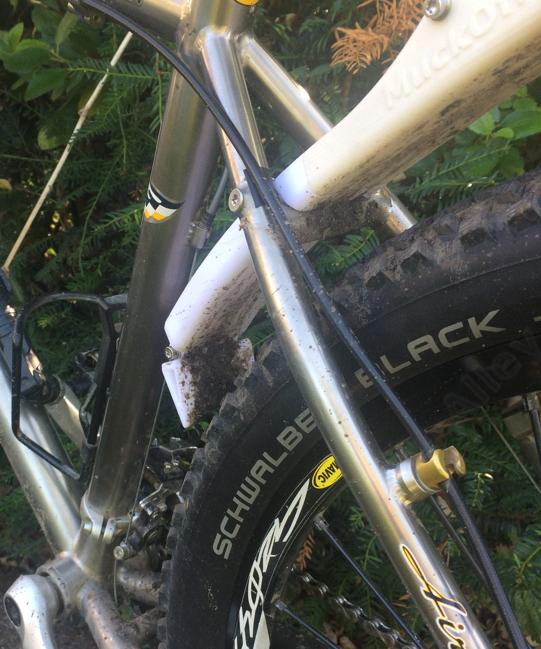
The spatter-pattern on the under-side of the mudguard, shows a central symmetrical line of mud along the length, which fades towards the left & right edges, suggesting that the mudguard is wide enough.
The mud-flap & the short transverse tube between the seat-stays clearly stopped a lot of mud. The front dérailleur-actuator survived with a light dusting, as did the seat-tube mounted water-bottle cage (you don't want to drink from a bottle that has been sprayed with cow-shit).
The evident deficiency was in the length; the saddle & my shorts were largely unblemished, but the back of my shirt stopped a fire-hose of mud.
The mudguard was silent (no rattling from the internal shock-cord), & there wasn't any obvious vibration.
Conclusion
Pros:
-
The mudguard shows little lateral (either sideways or vertically) or torsional flexibility.
The mudguard is silent; no rattling or creaking.
-
As required, the junctions between the three tubular sections can easily be dislocated, so after removing the wheels, the bike can be stowed in a bike-bag.
-
The mudguard protects the saddle (important if it's leather), the seat-tube mounted water-bottle cage, & to a lesser extent the front dérailleur-actuator.
Cons:
-
Compatibility:
- Tail-light:
-
The mudguard obscures any tail-light mounted low on the seat-post. Normally one would just slide the tail-light further up the seat-post, but in this instance the seat-post is a Thudbuster, the upper section of which implements a suspension-mechanism covered with a protective gaiter. Fortunately there are many commercially available tail-lights which are designed to mount onto the saddle-rails.
- Rear Pannier-rack:
-
In contrast to the tyre-hugging circular profile of a traditional mudguard, this volute shape is incompatible with pannier-racks.
- Bike-geometry:
-
The mudguard's design is specific to my bike's frame-geometry, which fortunately has a gap between the seat-stays of the same width as my rear tyre. Had the frame-geometry @ this point been narrower than the tyre, a significantly more complex geometry would have been required for the mudguard's leading curved tube. I've failed to describe such a curved wasp-waisted thin-walled tube, after several attempts with FreeCAD.
The mudguard is also dependent on the diameter of the rear wheel (unfashionably 26" counter to the current (2024) dubious hype around 29" wheels; why bother when a new diameter will be introduced next year).
- Rear Suspension:
-
It's probably not going to work with rear suspension. Even if there were equivalent seat-stays between which it could be mounted, the vertical acceleration of the rear wheel might induce an intolerable load on the mudguard.
-
The mudguard is rather heavy & despite finite-element modelling, I prefer to postpone any weight-loss program until it has been field-tested for a while … & perhaps needs to be rebuild for some other reason.
-
The front dérailleur-actuator is moderately protected, but some mud flings from the rear wheel in the short unshielded span between the mud-flap & the actuator.
The length of the mudguard is insufficient to protect the back of one's shirt.
-
In contrast to the plastics typically used in FFF, colouring of Nylon printed either by SLS or MJF requires post-processing (painting or dying), which costs.
-
The choice of brand-name didn't account for the annoying existence of a homonym lurking in the murky world of cleaning-products "Muc-off".
After the failure of the second version of this product to fit, I gave up for a while, muttering that it was a stupid idea in the first place. That admission of failure began to rankle, so I had a third go @ printing the part, which succeeded. I'm pretty pleased with the final result, but measuring the relative lengths of the above lists of Pros & Cons, it may be a path I travel alone.