
Prism Cells


Overview
This is a matrix of hollow sticks for insects to inhabit. Various sizes of hole are provided to suit different sizes of insect, but the outer dimensions of each stick are currently identical.
The matrix is tied to a pole or tree with rope. Each stick within the matrix can be split to permit inspection, which is typically performed in-situ.
Currently the sticks & the matrix are hand-made from wood, but since ≈200 sticks are required this is laborious.
Problems
-
Currently the sticks are contained in a square cross-section rectilinear grid. The consequence is that if an individual stick is removed for inspection, the column of sticks above can slide down unless another stick is inserted behind it for support. One might be able to solve this by removing the matrix from its post, then rotating it by 45°, but the process of re-attaching the matrix to the post is laborious.
-
Make the outer cross-section of each stick hexagonal, so that the gaps between sticks aren't straight.
N.B.: a circular hole more closely fits a hexagonal cross-section than it does a square (or triangular) one, so less material is required.
CAVEAT: the sides of the case would also have to zigzag, to avoid leaving any gaps.
-
The sticks probably have a top & a bottom, so ideally it shouldn't be possible to install them within the matrix @ any other angle.
-


Cross-sections which Tile but lack Rotational Symmetry To limit the permissible orientation of each stick, each could interlock with its neighbours like a jigsaw.
CAVEAT: the sticks on the outer edge of the matrix would have to interlock with the case.
CAVEAT: it doesn't prevent the whole matrix being installed upside-down.
CAVEAT: the width of the sticks is probably too small to include either a plug or socket.
-
The hole-sizes currently form an arithmetic sequence (perhaps to match Imperial sizes of drill-bits): i.e. six " steps spanning a 4-fold increase. This is probably suboptimal since the tolerance of an insect for a hole of the wrong size is probably a ratio of the insect's size. An insect preferring a hole slightly larger than , might have to accept a hole 50% larger @
CAVEAT: the bounds of this sequence are appropriate for species in the UK, & should be preserved.
-
Make the hole-sizes a geometric sequence spanning the same range (in the same number of steps, until the necessity to change arises), each of which would be times larger than the previous:

Thus the gap between adjacent hole-sizes is proportional to the size of the hole, & an insect seeking the optimal size of hole will never have to suffer one more than 26% too large.
Are the bounds & resolution of the sequence ideal or merely historical ?
-
The sticks need to be split for internal inspection.
-
Print the sticks in transparent plastic; the case could still be opaque to keep the inside dark.
CAVEAT: this may conflict with the identification solution.
CAVEAT: separation can't compromise the structure of any nest within, so sliding the halves apart isn't acceptable.
-
Rain-water could enter the holes when the wind-direction is unfavourable.
-
The case could have an overhanging roof to shed rain-water.
The overhang can't droop down, since that would thwart the removal of the uppermost sticks.
CAVEAT: wasps like to warm in the sun, so a shaded entrance-hole isn't ideal.
-
Sun-light may heat the case, making the interior uninhabitable.
-
Print the case in white to reflect incident radiation.
CAVEAT: a white case may be too visible, & perhaps light brown or grey may be a better compromise.
Create air-channels within the uppermost case-wall to inhibit heat-transfer to the sticks. N.B.: if the rain-roof is a separate part with an air-gap beneath, then they may not also be required in the main wall of the case.
-
Insectivorous birds could perch on top of the case.
-
Slope the top face of the case.
-
Tying the matrix to its pole is laborious.
-
Replace with Nylon cargo-straps with an adjustable plastic buckle. The case will provide something around which to wrap these.
CAVEAT: Nylon is hygroscopic & may therefore expand loosening the attachment.
-
A selection of hole-sizes is installed in any one matrix, but identification of the size of the hole in a specific stick may required a micrometer.
-
Print the hole-radius on the stick.
Sticks of similar hole-size could share a colour, thus permitting identification without removal. CAVEAT: this may conflict with the inspection solution.
-
As a stick is removed, the remaining sticks may shift fractionally as forces rebalance, requiring any replacement stick to be wiggled into place.
-
Chamfer the outer edge of the stick-ends, so that it tapers slightly.
CAVEAT: this will result in a narrow & shallow gap between the stick-ends.
CAVEAT: not possible when printing the sticks with the long dimension horizontal (they're too narrow to print vertically) & using FFF.
-
Sticks can fall from either the front or rear of the case.
-
CAVEAT: solutions remains elusive.
-
The number of sticks in the case could be increased to reduce the number of cases to be printed, or reduced to provide flexibility in their location.
-
The existing compromise () will be maintained.
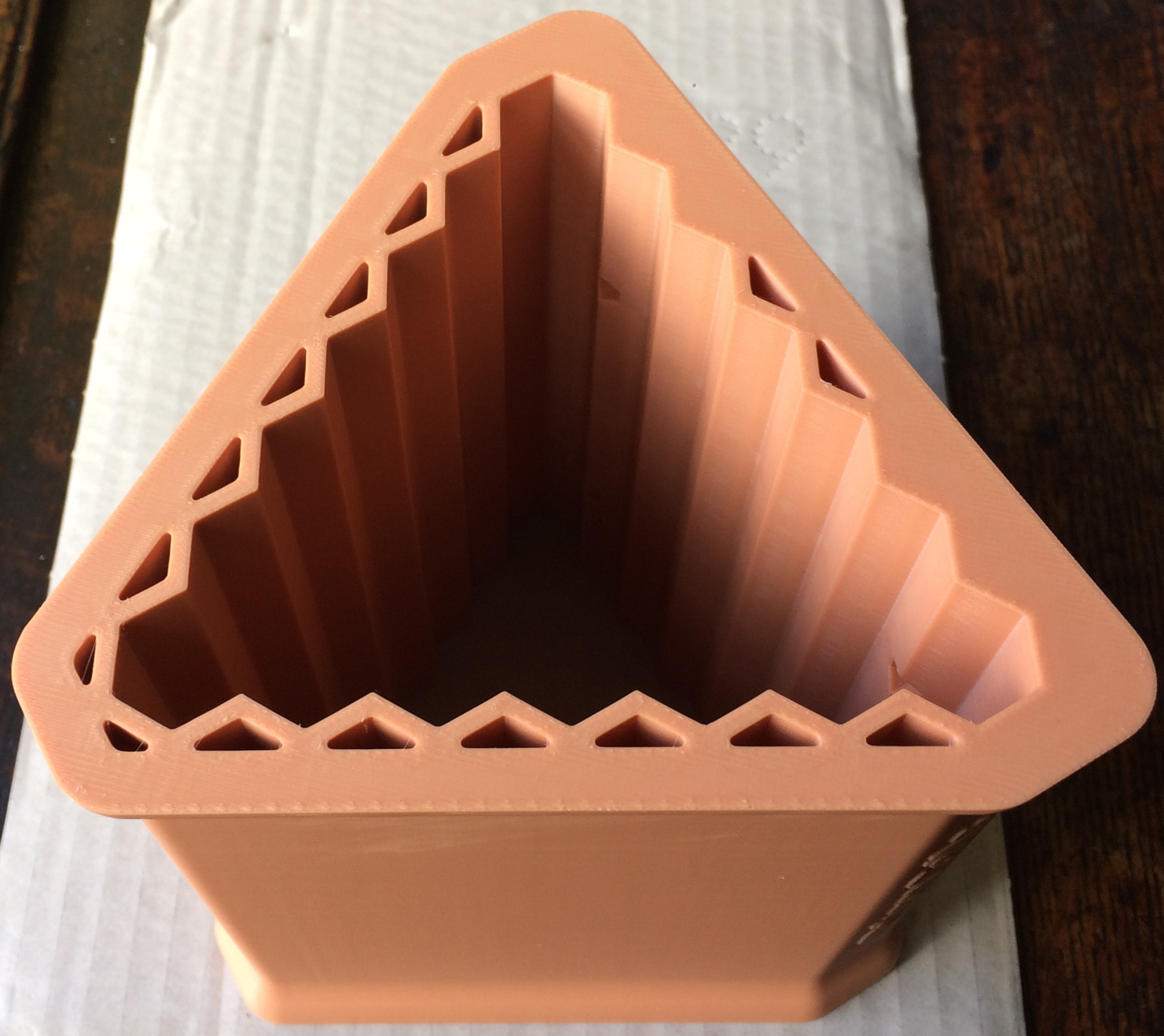
CAVEAT: hexagonal cross-section sticks can be conveniently assembled into an equilateral triangular case. The number of sticks in such a case is constrained to the Triangular Numbers, the nearest of which is 28.
-
v0.1:
-
3D Models


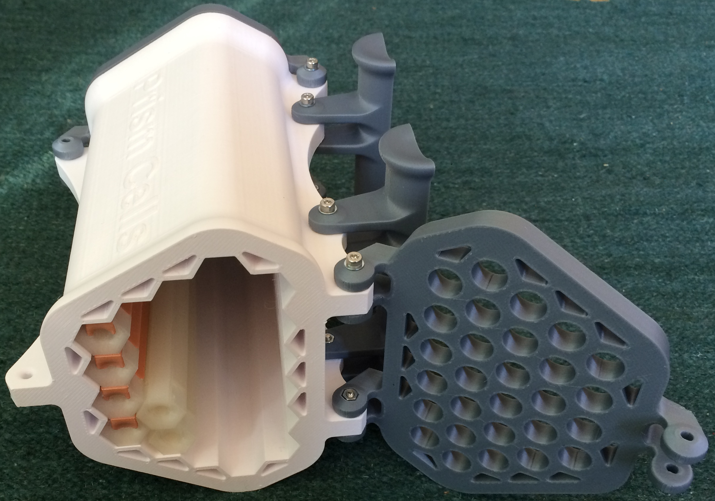
Not all my initial ideas could be embodied by this design, because to constrain cost it aims for fabrication by FFF. Neither the jigsaw lugs, chamfered ends, nor overhanging roof (though this might be provided as a separate part) proved possible.
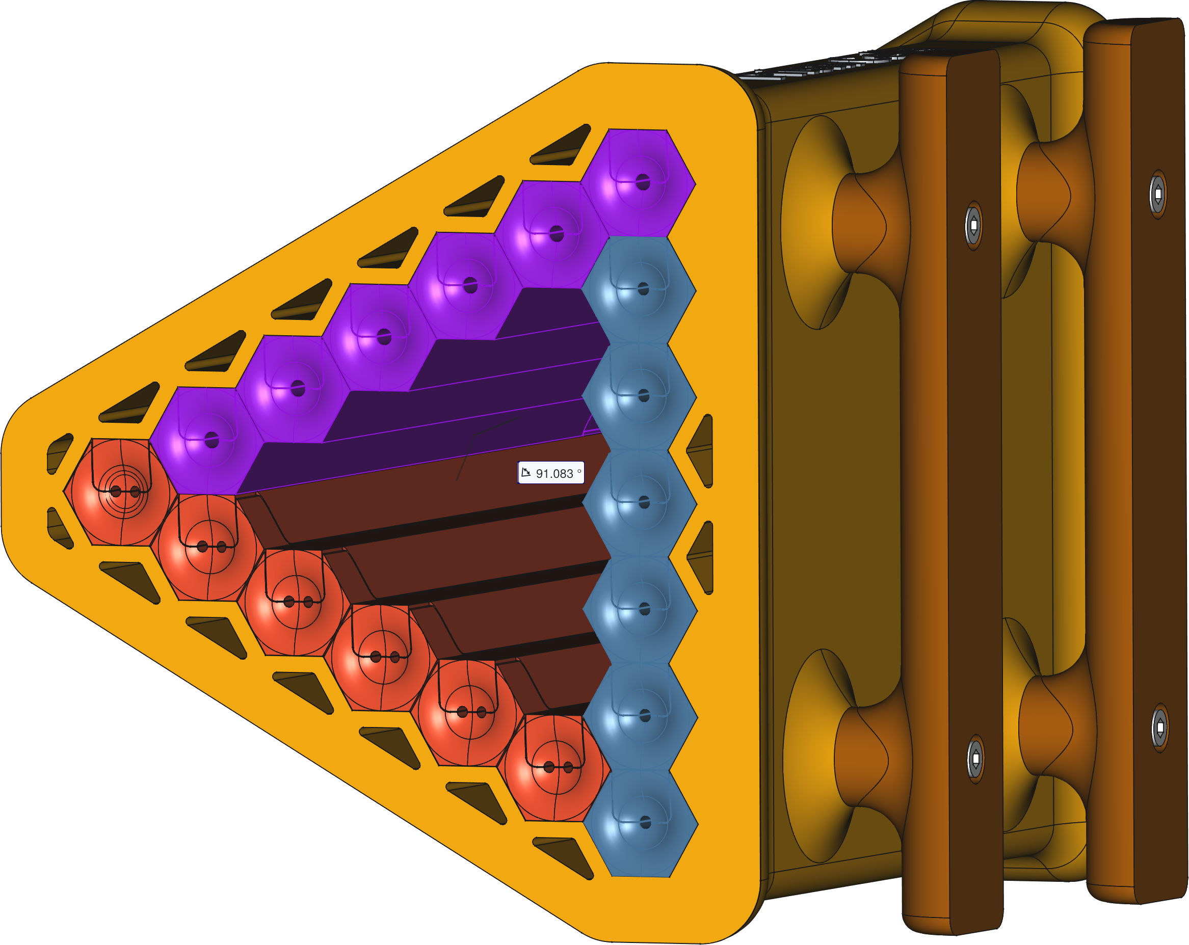
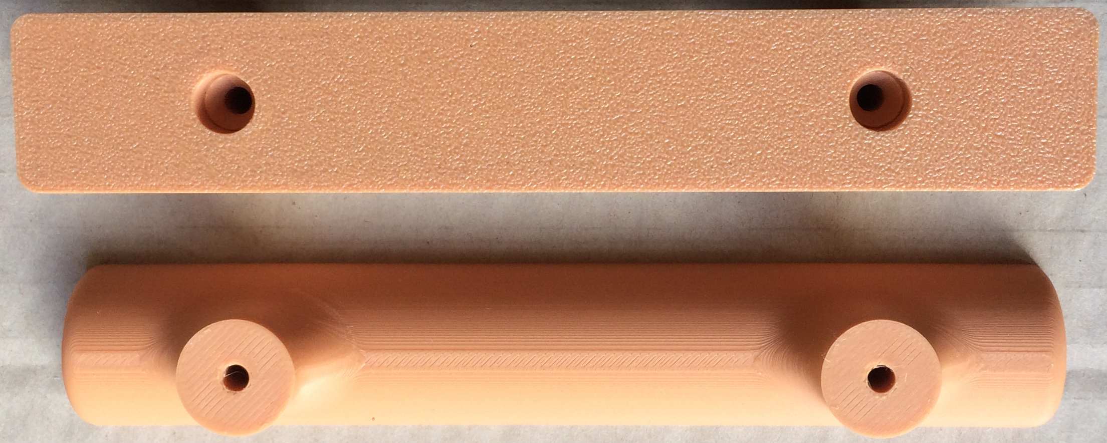
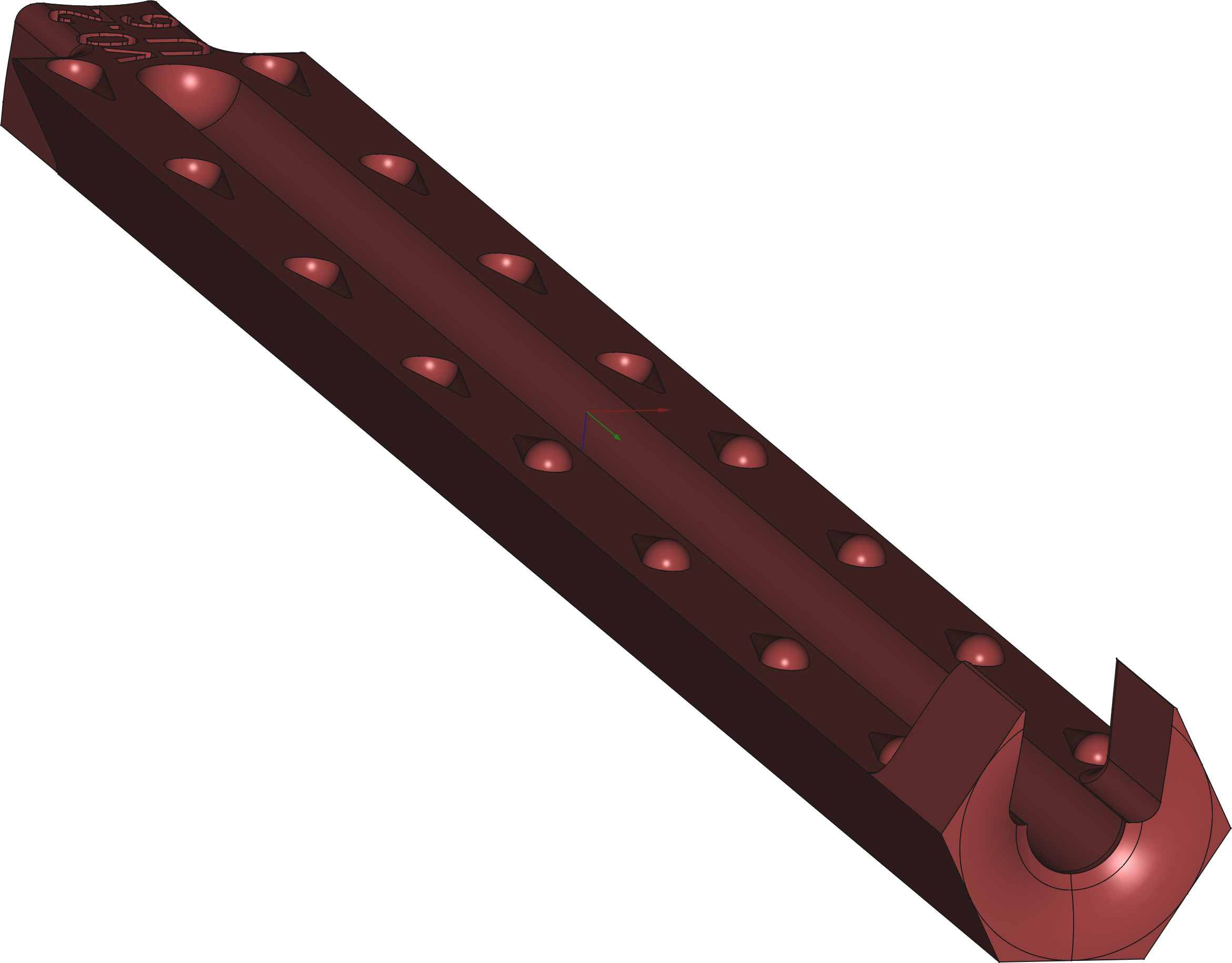
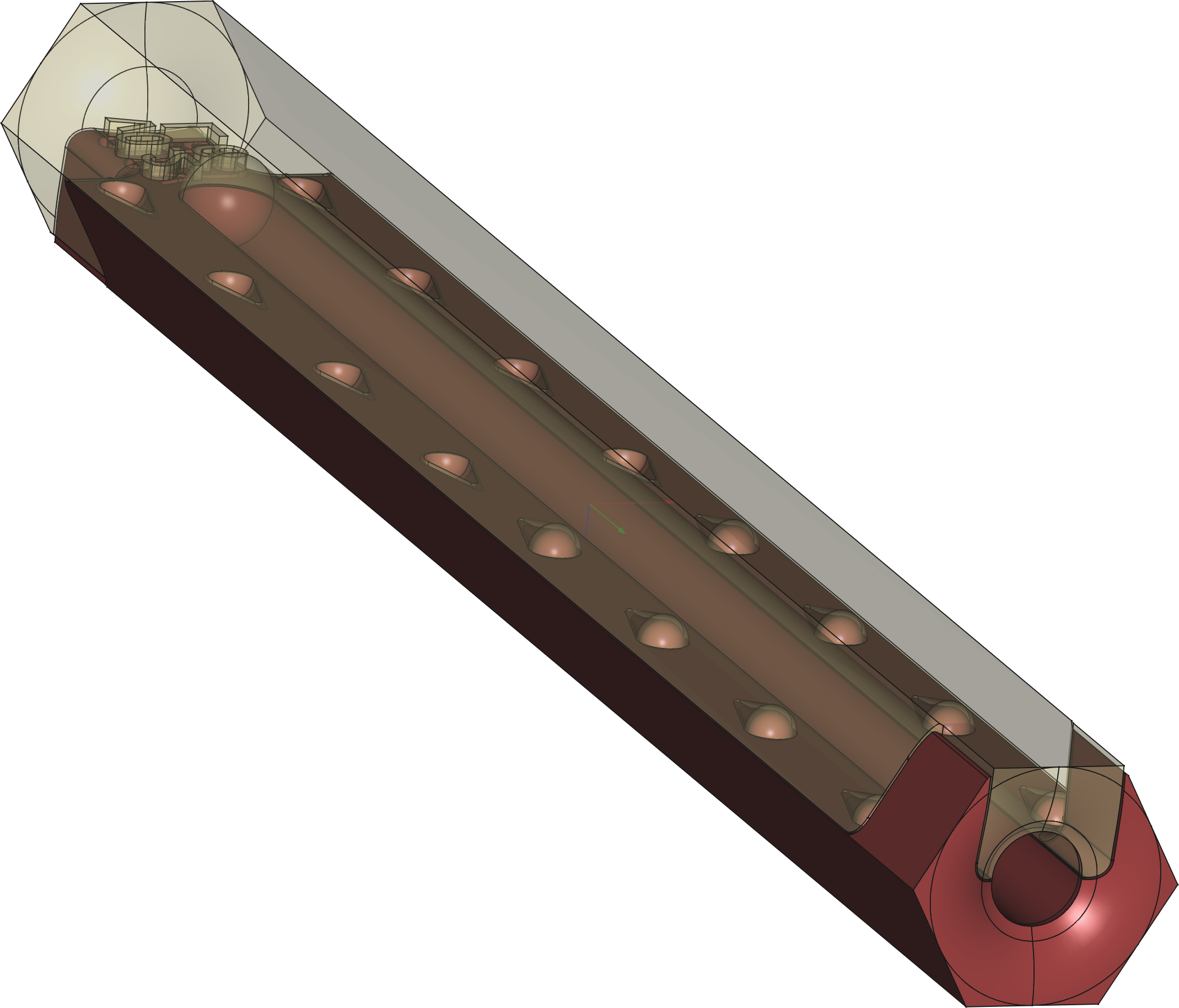
Each stick is composed from two halves (as for the original wooden model), which are designed to snap together. The interface isn't exactly rectangular because each jaw leans inwards by 0.15 mm so that it is inclined by 1.083° to the vertical. Separation can either be performed by sliding parallel to the long dimension, or pulling perpendicular to the interface, & to facilitate this each stick has terminal depressions (with which I can only sympathise). The two halves are asymmetrical, but only because the hole doesn't extend the full length of the stick. It is currently possible to connect mismatching halves, two lower, two upper, or halves with different hole-sizes. For this reason, the hole-size & whether it's the upper or lower half, is engraved on each part.
For the smaller hole-sizes, there's enough room in the uniform cross-section of each stick to accommodate two parallel holes. The downside is that these two holes can't be independently inspected, so it will be restricted to just the smallest (& least frequently used) hole-size.
Results


Manufacture
-
Material
-
PETG;
-
Colour
-
transparent for the sticks & brown for the remainder;
-
Infill
-
50% for the case & 100% for the remainder;
-
Resolution
-
0.1 mm for the sticks & 0.2 mm for the remainder;
-
Process
-
FFF;
-
Printer
-
Vendor
-
-
v0.2:
-
3D Models


Required Modifications
-
Sticks:
-
-
The two halves of each stick snap together & the sticks fit alongside each other in the case, but because the 0.1 mm precision with which they were printed is so good, they're just a shade loose. This may result in the two halves accidentally sliding apart as they're being removed from the case.
-
-
Reduce the clearance of the jaws which clamp the sticks together from 0.15 mm to 0.1 mm (resulting in a tighter fit).
-
Extra precision cost 5 USD per half stick, so print them @ standard 0.2 mm precision.
-
Add a saw-tooth pattern to the mating-surface of both halves to inhibit them sliding apart accidentally.
-
-
The mating-surface of each stick has a weave-like ripple, which may partially occlude narrower hole-sizes.
The halves don't mesh together perfectly, so that the measured height of the hexagon is 0.6 mm taller than the regular hexagon required (which exceeds the 0.25 mm inter-stick gap provided-for in the case).
-
FFF may not be suitable for printing smaller hole-sizes.
Reduce the height of both stick halves by 0.3 mm.
-
The text on each half stick, which identifies which half & the hole-size, is illegible, partly because of the surface-texture, but also because the font was only cut 0.5 mm into the surface.
-
-
Double the depth to which the font is cut into the surface material.
-
Minimise the number of characters.
-
Maximise the font-pitch.
-
-
The sticks aren't transparent as hoped, but @ best translucent (which is no use).
-
The additional expense of the transparent filament isn't worth it; one could use this as an opportunity to print the two halves of each stick in different colours to facilitate distinction & help with the illegible text.
-
-
Case:
-
-
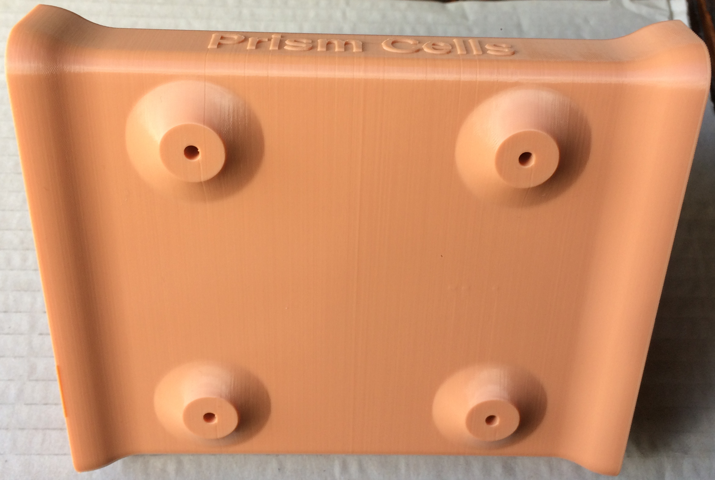
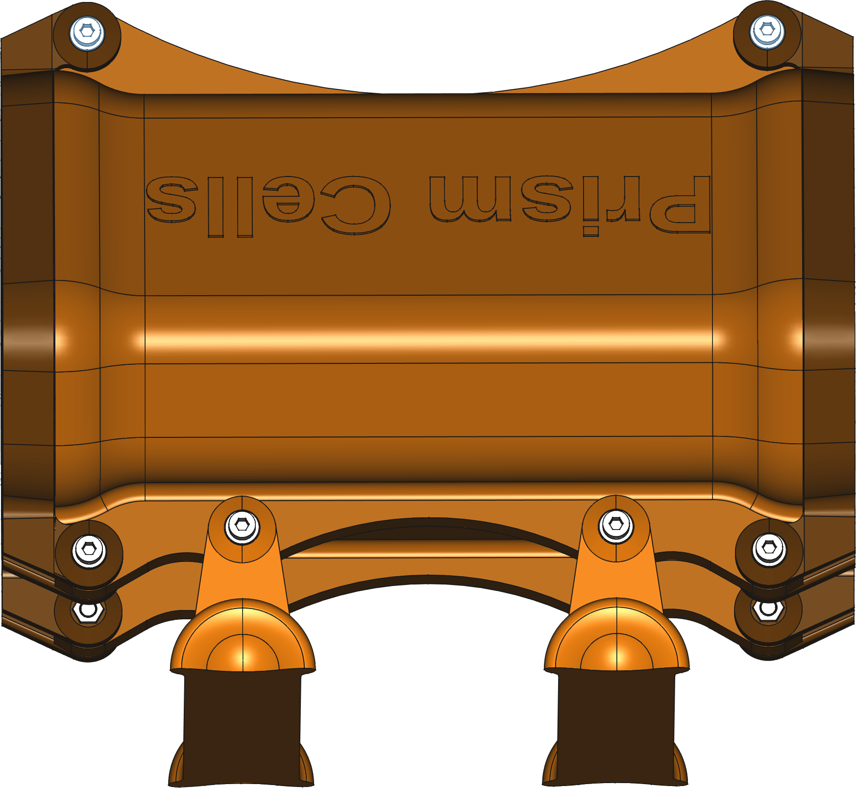
The case's colour isn't the expected brown, but rather Elastoplast pink. The idea was to help it blend into its woodland-environment rather than the local pharmacy, but this doesn't look like it will be effective.
-
The choice of brown severely reduced the available manufacturers, & a more commonly offered colour (like grey) might be almost as good.
-
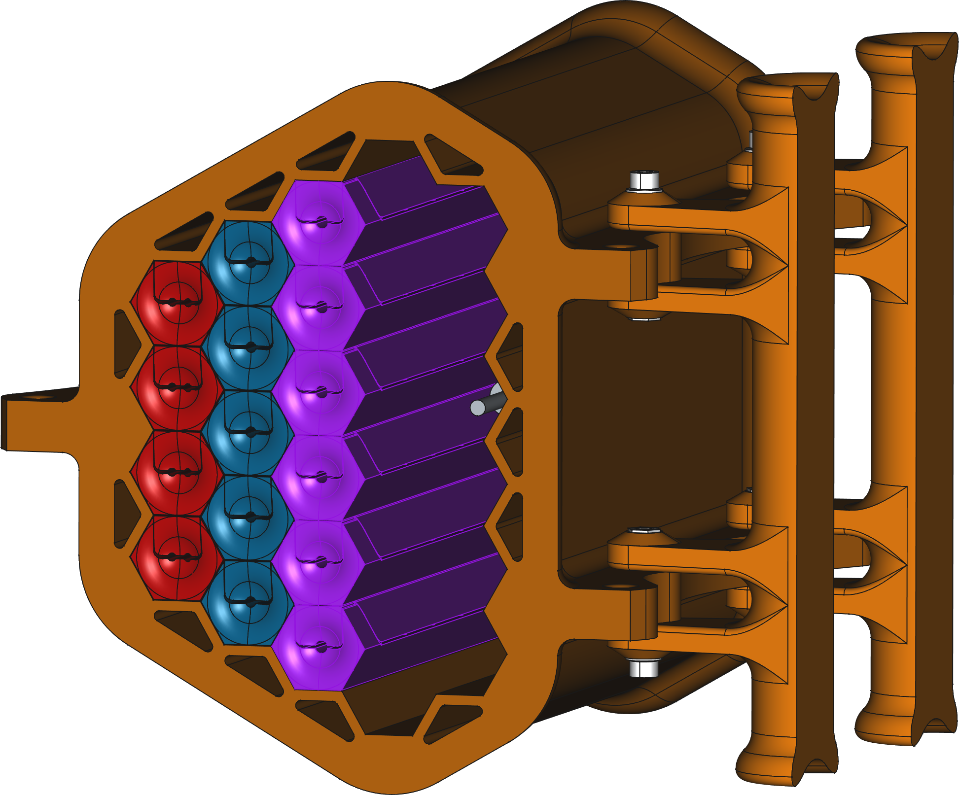
The case's triangular cross-section is an inefficient shape to contain the sticks; a more hexagonal shape could contain the same number of sticks in a shorter (cheaper) perimeter.
-
Remove the 6-stick equilateral triangle @ the apex furthest from the handles & redeploy them as a 6-high column on the other side, which reduces the perimeter (the outer edges of the fagot) from 42 hexagon-sides to 38 (a 9.5% reduction).
-
The gap between sticks in the case is 0.25 mm, in the hope that this is both large enough to cater for manufacturing errors, & small enough to jamb the sticks in place so they don't fall out with every puff of wind. This compromise is going to fail, I just know it.
-
Add a mesh guard to either end of the case, which inhibits access neither by insects nor humans, but prevents the sticks from being removed.
One should be able to remove the guard (permitting access to the sticks), without fiddling with nuts & bolts, while balancing on one leg, @ the dangerous end of a ladder. For this reason, the single bolt furthest from the handles, doesn't have a nut, but merely acts as a locking-pin.
-
-
Handles:
-
-
To bolt the handles in place involves threading a nut onto a bolt as it emerges on the inside of the case (where there's a hexagonal recess to receive it); this is slightly tricky.
Steel M3 × 30 mm hex-socket cap-head bolts were used, with a washer to distribute the load of the bolt-head (there's none @ the nut end because it's incompatible with the hexagonal recess). These will rust, which is not just unsightly but makes them difficult to undo.
-
All fasteners in this design are stainless steel. M3 × 25 mm hexalobular internal cap-head bolts (which are more difficult to round, but require a T10 bit rather than a 2.5 mm hex-key), with Nyloc nuts.
-
Where cable-ties are used to attach the handles of the case to a tree, there's a tendency to slip off the end of the handles.
-
Put end-stops on the handles.
-
Since the radius of the vertical post to which the case is tied is unknown & could therefore be narrower than the space between the handles, the handles could be pulled together by the rope which passes around the back of the post. The resulting stress depends on the rope-tension, which could be considerable.
-
Mount the handles on vertical axis hinges to permit the horizontal distance between the handles & their angle, to change. The distance between the handle & post won't change much, since there's only 3 cm from hinge-axis to bar-axis, but the bending-moment on the lever-arm will reduce as it aligns with the tensile force of the rope.
-
Stress
Stress in the stick Hole-radius
Force
Displacement
Stress
mm
N
mm
MPa
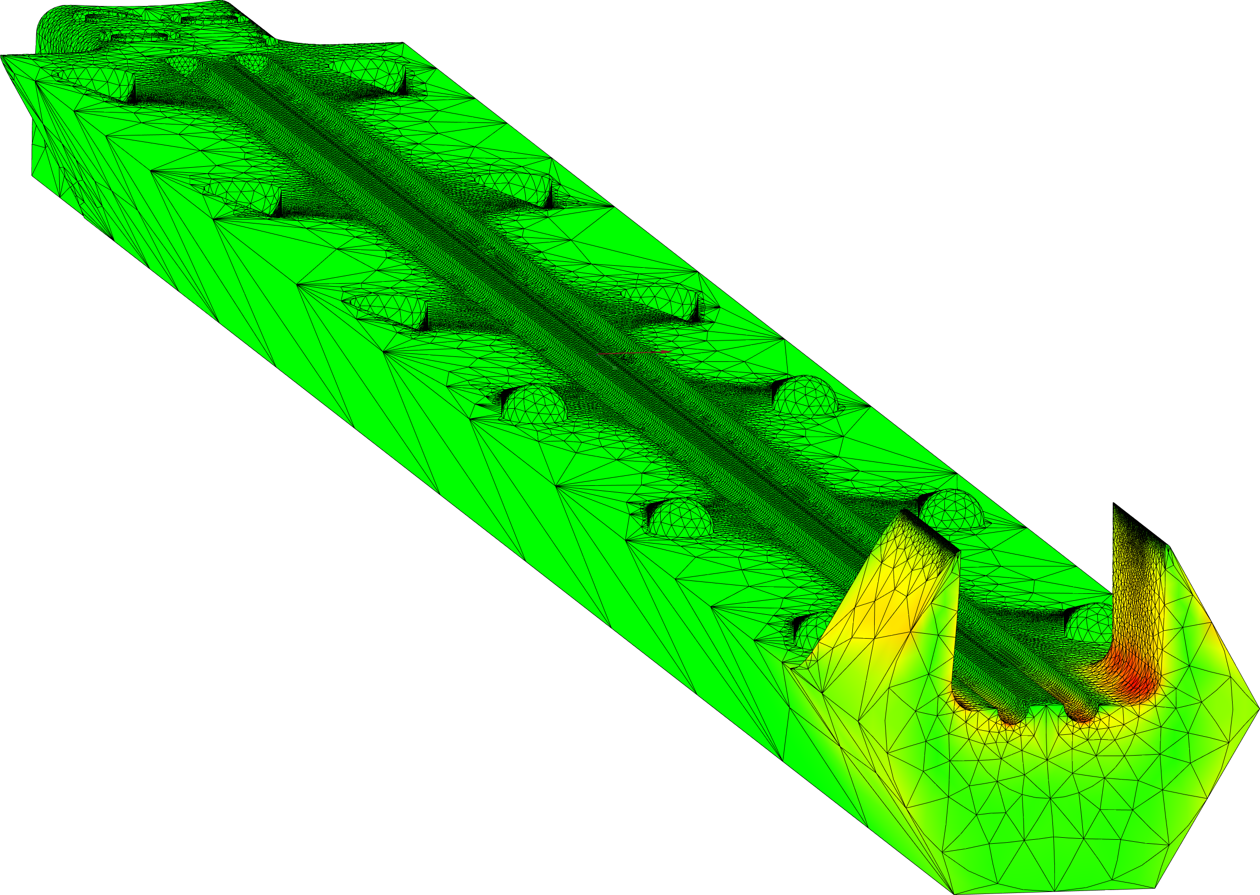
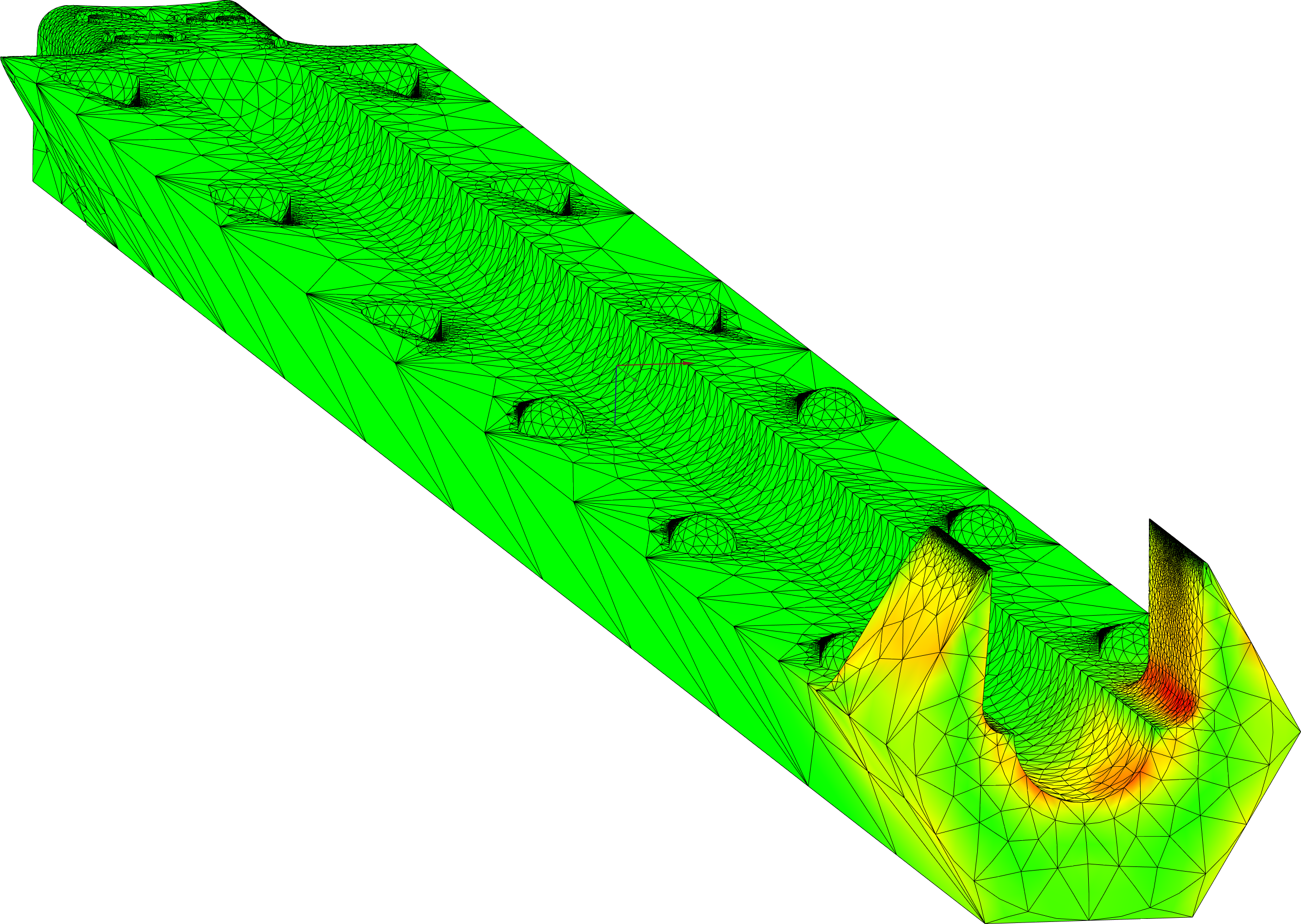
0.79375 35 0.15 11.3 3.175 28 8.6 The stress has been modelled using the finite element method, to determine whether the jaws can survive the process of snapping the halves together. The analysis suggests that from application of an outwards force of 35 N separating the jaws (a smaller downwards force on the top half will be magnified by wedging action), each jaw expands by the 0.15 mm required to snap into place, resulting in a Von-Mises stress of 11.3 MPa. The flexibility of the jaws increases with the hole-radius. So @ the maximum hole-radius, the force required for the same expansion reduces to 28 N & the stress to 8.6 MPa. Since the part will be printed while horizontal, the force separating the jaws lies within the plane of the layer-boundaries. In this regard the UTS for PETG of ≈55 MPa is unrealistic, but possibly adequate (assuming they're 100% infill).


Stress Part
Force
Direction
Displacement
Stress
N
µm
MPa
Guard
10 Y (perpendicular to plane)
1800 7.8 Z (in plane)
193 4.6 Handle
50 X (parallel to bar-axis)
47 4.5 250 X (perpendicular to bar-axis)
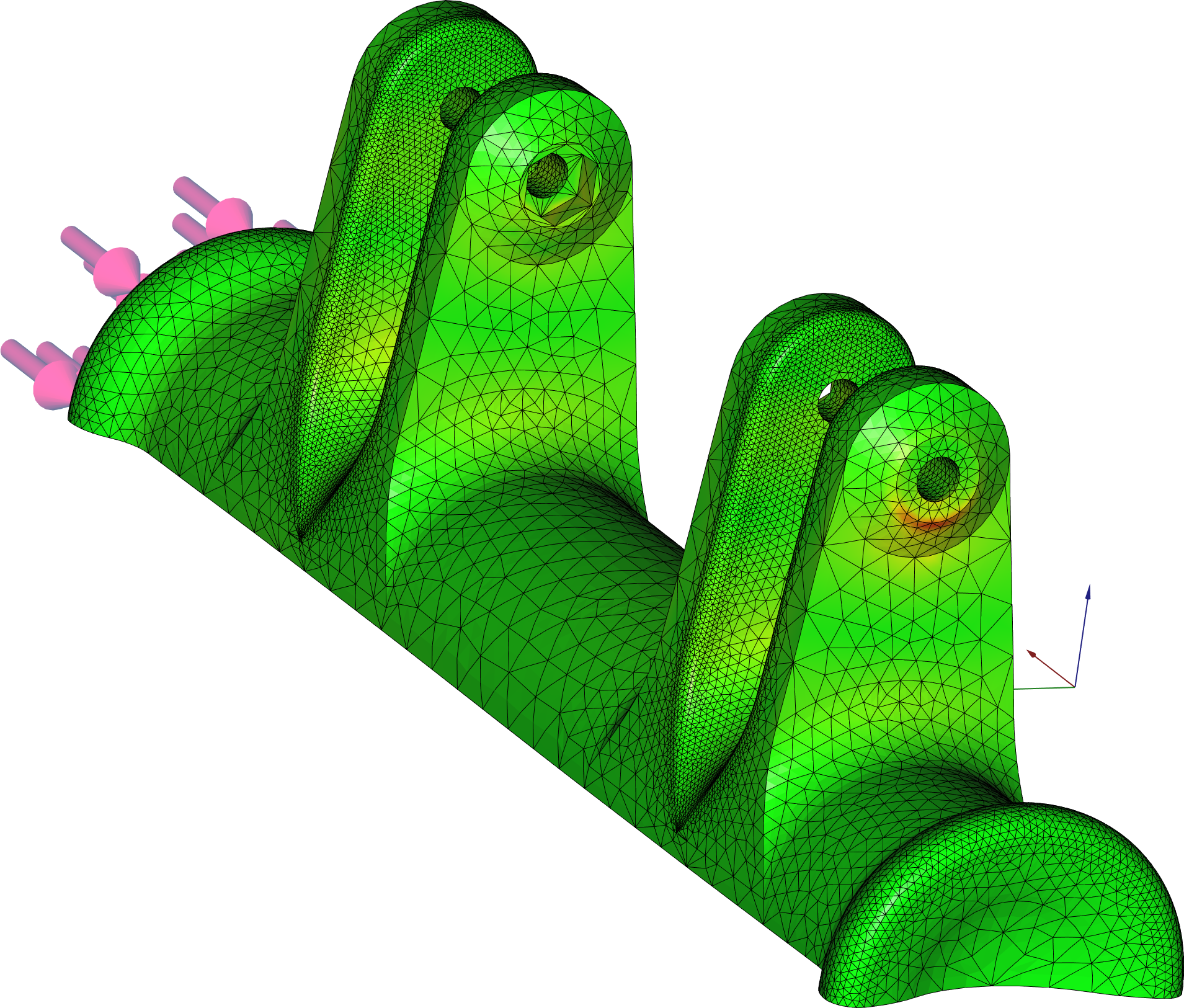
54 4.7 The Finite Element Method was used to model the peak Von-Mises stress.
On the basis of a 10 N force:
-
levering the guard open against a seized hinge, which predicts that the guard bends 1.8 mm, resulting in a stress of 7.8 MPa around the hinge.
-
pulling the opened guard perpendicular to the hinge-axis, which predicts that it bends 0.19 mm, resulting in a stress of 4.6 MPa around the opened hinge.
The case's handles are designed to be tied to a post of unknown radius, & for that reason each can pivot about the vertical axis & yield to the (ill-defined) force resulting from rope-tension between them.
-
A 50 N force pulling down along the length of the handle, as though a weight was hung from the case, resulted in a predicted stress of 4.5 MPa.
-
On the wild assumption of a 250 N force, spread over the hemi-cylindrical surface pulling the handle away from the case, the analysis predicts a stress of 4.7 MPa around the bolt-holes.
In all four cases, the distortion depicted has been magnified 25-fold.
Though these stresses should be tolerable, the force used to generate them was arbitrary.
Results


Manufacture
-
Material
-
PETG;
-
Colour
-
-
Case:
-
White
-
Handles & Guards:
-
Grey
-
Sticks (Lowers):
-
Brown
-
Sticks (Uppers):
-
Natural
-
-
Infill
-
100%;
-
Resolution
-
0.2 mm;
-
Process
-
FFF;
-
Printer
-
Vendor
Observations
-
Sticks:
-
-
The saw-tooth patterning on the mating-surface of the sticks worked as required to prevent the sticks accidentally sliding apart.
-
The tighter jaws on the sticks worked as required, making the sticks harder to separate. It may actually be too hard with cold fingers, but it probably won't be deployed in cold weather.
-
The reduced height of the hexagonal cross-section was exactly that required to create a regular hexagon after accounting for a slight horizontal gap between the halves. A column of four sticks can now be stacked into the case.
In the other direction (where no geometric correction was applied), a row of four sticks wedges into the case. It's rather tight, but I don't think it requires remedial action.
-
The cost-saving attempt to print the sticks @ the same standard 0.2 mm resolution as the other parts, has been largely successful. They're definitely not as high quality, but they're adequate quality & substantially cheaper.
-
The smallest hole-size printed OK, but the crack between the stick halves, resulting from the surface-texture, joins the two holes.
-
The larger font on the sticks was more legible, but only to the extent that some information could be extracted from the brown (lower half) sticks. Regrettably, the font on the natural colour sticks was still illegible.
It didn't help matters that instead of printing the requested hole-sizes two each of [0, 2, 4, 6], I received three of size 6 but only one of size 4.
-
-
Case, Handles & Guards:
-
-
The case, handle & guard have bolt-holes, all of which during printing, have a horizontally orientated (i.e. unsupported) polar axis. The result is that they are all visibly oval, but no reaming was necessary before inserting either bolts or nuts.
-
Weights & Measures Part
Calculated Volume
Estimated Density
Infill-ratio
Calculated Weight
Measured Weight
cm³
g / cm³
g
Case
358.2 1.27 1 455 752 (inc. 8 fasteners) Handle
41.7 Guard
69.3 Stick
14.0 to 15.7 35.5 The predicted weight corresponds closely with the measured value, which confirms that the parts were printed @ the requested 100% infill (I've been duped before). The assembled case, guard & handles (but without any sticks), weigh 752 g & each stick (two halves) 35.5 g, therefore a hefty 1.746 kg when fully populated. It feels slightly over-engineered, but the cost-saving from printing @ a lower infill-ratio, is hard to justify when compared to the effort required to replace a part some slack-jawed oaf sat on.
The guard could be thinner if it proved to inhibit habitation.
-
One of the three hinges, on one of the two guards, warped slightly where it emerged from the build-plate.
This is a relatively common problem with FFF, resulting from cooling (& therefore contraction) of the filament as it hits the build-plate, then curling as the contracted layer tugs @ those beneath, & potentially fouling the print-head as it traverses the same spot on subsequent layers. In this instance the warping only affected a sixth of the hinges & the part was still usable, but some minor redesign seems prudent.
-
-
-
v0.3:
-
Required Modifications
-
The rope used to secure the assembly to a post, will need to be tight enough to resist the weight of the assembly, which @ 1.746 kg is rather heavy.
-
Reduce the weight by specifying a lower infill-ratio.
CAVEAT: this has minimal impact on either weight or cost, because the largest part (the case) has few large volumes to hollow, & it will also have a small negative impact on strength.
-
Sticks:
-
-
Increase the gap between the two parallel holes in the small stick.
Consider abandoning the smallest hole-size, the details for which appears to be on the limit for FFF.
-
To make the font on the sticks more legible, favour darker colours so shadows help to delineate the letters; avoid translucent colours.
Separate the strings representing version & size, by moving one to the middle of the stick, to allow both pieces of information to be rendered in a larger font.
-
There are 14 half sticks to be printed, plus two each of handles & guards, & the case. The total of 19 mesh-files to upload to the manufacturer leads to confusion & errors. Mesh the sticks in compatible pairs to ensure that the results are all usable.
As a side-effect, any two compatible stick-halves must have the same colour, so colour can alternatively be used to differentiate hole-size; though there aren't 7 suitable colours of filament from which to select.
The downside is that any error in printing one half stick, will require both halves to be restarted. So whilst one could also opt to mesh the handles as a pair, to further reduce the number of mesh-files, this is a larger & therefore more error-prone part, which changes the balance towards printing individually.
-
-
Guards:
-
-
The horizontal area of the guard's hinges adjacent to the heated build-plate, will be marginally increased to enhance adhesion & therefore inhibit warping.
-
Results


Manufacture
-
Material
-
PETG;
-
Colour
-
-
Case:
-
White
-
Handles & Guards:
-
Grey
-
Sticks:
-
In contrast to v0.2 where colour was used to distinguish the two halves of any stick, colour in v0.3 is used to distinguish hole-size. Because the number of suitable colours is lower than the number of hole-sizes, substantively different hole-sizes (where the distinction should be obvious) may share a colour.
Hole-size Colour-code Hole-size 00 1 2 3 4 5 6 Colour White
Grey
Brown
Black
White
Grey
Brown
-
-
Infill
-
75%;
-
Resolution
-
0.2 mm;
-
Process
-
FFF;
-
Printer
-
Vendor
Observations
-
Weights & Measures Part
Calculated Volume
Estimated Density
Infill-ratio
Calculated Weight
Measured Weight
cm³
g / cm³
g
Case
358.2 1.27 0.75 341.2 315 Handle
41.7 70 Guard
70.3 125 Whole Stick (size-3)
30.9 29.4 26.8 Fully populated total (excluding fasteners)
1378.6 1260 The consistent small discrepancy between calculated & measured weights suggests that either the material-density was lower than estimated or they were printed @ an infill-ratio of 70% (no big issue).
The total weight of a fully populated case was measured @ 1.493 kg (including fasteners).
-
The only visible flaw in this print, was distortion of those holes which were printed with a horizontal axis; this is an unavoidable (but tolerable) consequence of using FFF.
The warping previously observed in one of the guards is no longer apparent.
-
This is the first time a full complement of sticks has been installed into the case, & they fitted satisfactorily.
Regrettably, the sticks also slide out the case quite easily because of the slick nature of the material. I wouldn't want to risk reducing the inter-stick gap any further, but the guards on the case-ends prevent this occurring accidentally.
The two halves of each stick snap together, but a horizontal gap can still open between them.
-
Pairing the halves of a stick into one file successfully reduced the complexity of the order, but inexplicably I still ended up with one unpaired half ?!
Several extra size-00 sticks were delivered; presumably these were test-runs.
-
The engraved size of each stick is now legible.
-
-
v0.4:
-

Required Modifications
-
Limit the potential for any horizontal gap to open between the stick-halves:
-
Marginally tighten the jaws terminating each stick, by increasing the extent by which they slope inwards from 0.15 mm to 0.2 mm.
The close packing of sticks within the case, forces them together. The surface ripple observed on each v0.2 stick was only half as high in v0.3, resulting in excess vertical space. So as a compromise, reduce the height-correction introduced in v0.2, by 25%.
-
Inhibit the tendency of the sticks to slide from the case:
-
Increase the inter-stick friction by scoring fine vertical striations onto the exterior surface of each stick. The print-head will (during its horizontal traverse along the length of a stick) resonate after passing each striation, creating both indents & subsequent outdents.
CAVEAT: the printer may be better than expected.
Results

Manufacture
Same as for the manufacture of v0.3, except 70% infill.
Observations
-
Weights & Measures Part
Calculated Volume
Estimated Density
Infill-ratio
Calculated Weight
Measured Weight
cm³
g / cm³
g
Whole Stick (average of sizes [3 … 6])
29.92 1.27 0.70 26.60 30.75 -
The two halves of each stick snap together, but still insufficiently tightly to prevent a horizontal gap opening between them.
-
The striations previously introduced increase inter-stick friction to some extent, but the sticks still slide from the case rather easily.
-
-
v0.5:
-
Required Modifications
-
Further limit the potential for any horizontal gap to open between the stick-halves:
-
Marginally tighten the jaws terminating each stick, by increasing the extent by which they slope inwards from 0.2 mm to 0.25 mm.
Reduce the height-correction introduced in v0.2, by 50%.
-
Further increase inter-stick friction:
-
Double the depth of the striations, from 0.125 mm to 0.25 mm.
-

|
Stick of Hole-radius (mm) |
||||||||||
|---|---|---|---|---|---|---|---|---|---|---|