
Artificial Wasp-nest

Overview
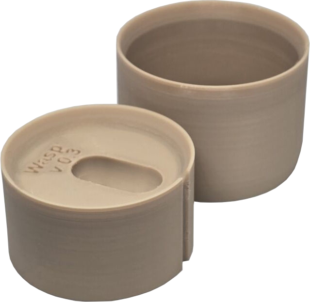
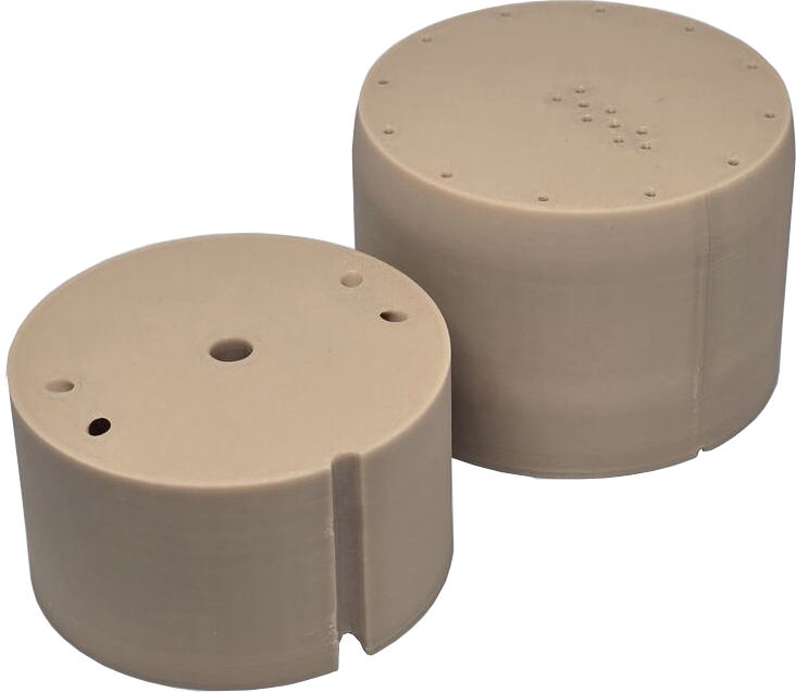
This is a copy of the burrow typically made by ground-dwelling wasps. It consists of a narrow cylindrical vertical entrance-hole which descends to a wider lozenge-shaped chamber. The wasp drags a grub down into the chamber, to use as a food-source for its larvae.
Normally the earth in which this dwelling has been dug is porous, allowing some air & rain-water to permeate.
The initial models were plaster-casts, which have the advantage of being porous, but were fragile, & unsuitable for larger scale fabrication. The top of the plaster-cast is covered with a divot removed from a real nest. The divot is cut using an aluminium cylinder, which doubles-up as the outer structure containing the plaster-cast. The plaster-cast is formed from an upper & lower part, allowing separation for inspection, & for this reason the upper cast has wire handles embedded.
Design-criteria
-
The nest has a small declination from the entrance-hole of ≈10°.
-
Use a circular cross-section since an aluminium pipe is used to pilot the hole in the ground.
-
Try to match the outer radius with the current aluminium pipe.
-
Force rotational alignment of the parts preventing arbitrary relative orientation.
-
The entrance-hole hole must be central to the circular cross-section.
-
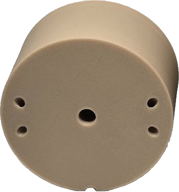
Design to expel rain water.
Drainage-holes are required, but must be sufficiently small to block access by ants.
-
The enveloping tube must exceed the height of the cap by ≈10 mm, to contain the extracted divot.
-
The cap must have an extraction-mechanism. Ideally this should be replaceable & minimally obstruct the placement of the divot.
Other Design-considerations
-
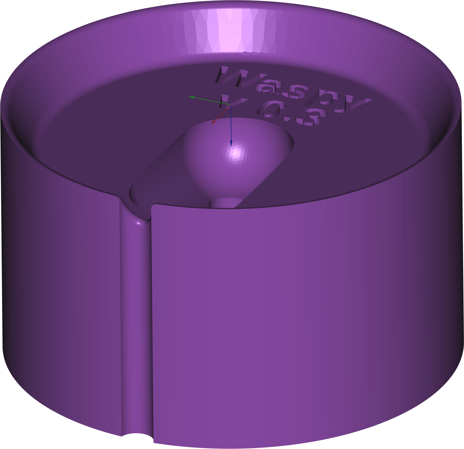
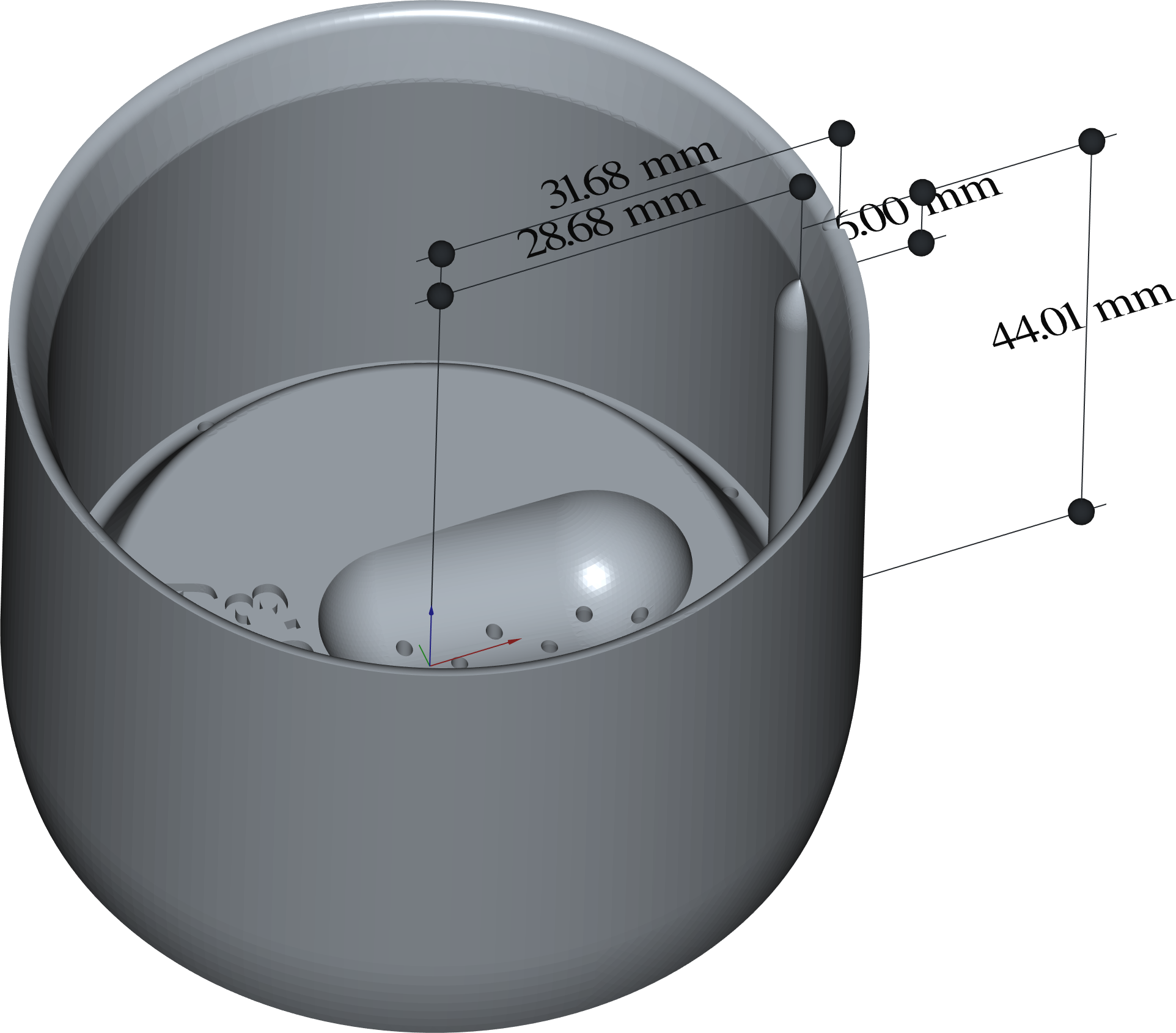
I've chosen to model the nest as two hemispheres connected by a cylinder. This is tilted down by the required declination angle then the entrance-hole is modelled as a cylinder poked vertically into the apex of this structure. It's difficult to tell from the plaster-cast whether there's a more appropriate geometry.
-
Because the wall-thickness is necessarily larger than the stronger aluminium tube it replaces, the inner radius of the plastic cylinder is smaller than the aluminium tube. For this reason, a divot cut from the ground using the aluminium tube will be slightly large, but one could either squash it into the flared rim of the base part or merely place it over the outer radius.
-
The interior area is further reduced by an annular moat designed to expel water, but there was still sufficient space to include the nest.
-
The key designed to constrain rotation of the cap relative to the base has been designed to provide visual confirmation that it's correctly orientated.
-
The cap has been wasp-waisted to reduce the volume of plastic required.
CAVEAT: this has been deprecated, to avoid creating a void in which predators may lurk & conspire.
-
Since the material is impermeable, some provision has to be made for oxygen. For oxygen to enter, carbon-dioxide has to be removed. So as CO2 being denser, dribbles out the drainage-holes @ the bottom of the nest, air can enter through the entrance-hole.
CAVEAT: this flow may stall if capillary-action draws water up into the drainage-holes, blocking them off. Putting the nest on top of sand may solve this problem … if it actually is a problem.
-
The base should be tapered to facilitate insertion into the ground.


Process
Provided that the cap's mesh is inverted (so that both parts are built with the nest facing upwards), the geometry is largely suitable for production via cheap FFF, only the toroidal channels used to insert handles, present an (insignificant) unsupported overhang. There's little justification for use of more precise, flexible & expensive processes like either SLS or MJF.
Infill
FFF offers the concept of infill, which is the automatic replacement of any large internal volumes of plastic, with a honeycomb-structure. This saves on plastic & print-time, but has an unpredictable effect on strength. Infill can range from 20% to 100% (@ which point the concept is absent). Depending on the manufacturer & the material, this can reduce the cost slightly. Depending on the manufacturer, the instruction is ignored anyway.
Material
- Nylon
- PETG
-
Nearly the ideal material for FFF, unless elasticity is required.
- PLA
-
-
Cheap, & therefore useful for prototyping.
-
Biodegradable.
-
- TPU
-
-
Flexible (depending on the brand of fibre).
-
Pretty tough.
-
- ABS
-
-
Slightly flexible, because the material includes butyl rubber.
-
Creates horrible fumes during manufacture, so it might smell a bit when cooled.
-
Prone to warping during manufacture.
-
Not as tough as reputed, due to the limitations of FFF.
-
Strength
The strength-requirements of this product aren't obvious; it just sits in the ground unless some oaf steps on it. The strength of the various materials can't be considered outside of the context of the production-process. For FFF the strength of all materials is levelled by an inherent weakness between the build-planes; a chain is only as strong as its weakest link. For parts produced by SLS there's only a slight anisotropy, & none for those using MJF.
Colour
Powdered Nylon doesn't normally include any dye; it must be painted … & that's expensive. HP PA12 is dyed so that it absorbs infra-red & is therefore always dark grey. PETG & PLA filaments are typically available with a wide variety of dyes; though these can affect material-properties to an undocumented extent.
TPU, PETG & PLA can be transparent, though infill will distort the image. It wouldn't necessarily be an issue for the wasp, since the enclosure is covered by a divot, but some inspection of the interior may be possible.
3D Models
There are three different types of model available here; STL, 3MF & FreeCAD. The first two are alternative descriptions of the mesh required by a manufacturer of your part, the last is the CAD from which meshes can be derived. 3MF is more concise & precise than the traditional STL format, but some web-sites (PCBWay) still don't accept it & those that do often have trouble displaying an image of your uploaded part, (which is useful to confirm that the cap has been inverted as required in FFF to avoid an unsupported bridge). FreeCAD is a large piece of s/w & it takes a lot of experience to drive without breaking the model, but time invested here is generally useful. There is lots of good documentation & an active group of responsive developers.
It's your choice whether you rely on me to print parts as required, upload meshes to the chosen manufacturer yourself, or go all in & adopt the FreeCAD model.
The cheaper manufacturers may be just some oik with a printer, so occasionally the part will be poorly manufactured; it's infrequent & I've always got my money back. They'll probably also give free advice on whether they think the model will print OK or can be improved.
Results
- v0.2
-
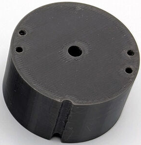


Printed in grey PETG, using 40% infilled FFF, on an "Original Prusa i3 MK3s", by "Seaside 3D".
Required Modifications
-
There are significant striations on the horizontal surfaces.
-
Request a narrower nozzle on the printer or a slower print-speed. Another manufacturer might configure the printer differently.
-
The colour is rather dark.
-
Regrettably, not many manufacturers offer brown PETG.
-
The tube-walls were considered too thick to pass muster from the wasp's perspective.
-
Reduce the tube-wall from 5 mm to 3 mm.
Since the old aluminium tube was only 1.5 mm thick, & this is too thin to print reliably, the wall of the plastic tube will be tapered from the new 3 mm over the vertical distance of the divot, to match the aluminium only @ the very top.
-
The narrow drainage-holes closed off during manufacture, because the FFF process tends to squish the first layer.
-
Make them conical, small @ the upper end, but with enlarged radius as they emerge onto the build-surface.
The base could benefit from a smaller nozzle-radius.
CAVEAT: there's no mechanism to explicitly specify this criterion on most platforms; it has to be communicated after selecting a manufacturer, & accepting a possible surcharge.
-
The height of the cylindrical entrance-hole was considered smaller than the plaster model.
-
Increase height from 23 mm to 27 mm.
-
The vertical space available to accommodate a divot was considered excessive.
-
Reduce height from 10 mm to 6 mm.
-
It was difficult to thread Nylon through the 180° toroidal channel.
-
Raise the channel slightly, leaving a smaller segment of the major radius for the thread to negotiate.
-
The Nylon thread handles were considered to interfere with the divot.
-
Tilt the toroidal channel by 30° about the non-polar horizontal axis, so that the Nylon emerges slightly outwards rather than vertically upwards.
-
The orientation of the key isn't visible when the divot is in situ.
-
Add an indicator-notch to the outer edge of the enclosing tube.
-
Results
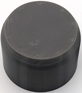
- v0.3
-
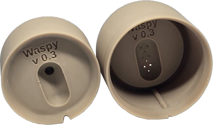
Printed in brown PETG, using 40% infill & a 0.2 mm nozzle for the cap & 100% infill & a 0.1 mm nozzle for the base, using FFF, on a "Bambu Lab X1 Carbon", by "Temprint".
Observations
-
The print-quality looks much better, probably because of the narrower 0.1 mm nozzle, but the change of printer may have made some difference.
-
The new sandy colour looks more natural.
-
The outward tilt of the toroidal channel is visible in the non-circular exit-holes in the cap.
-
The new conical drainage-holes appear to have remained open, but I can't currently tell if all of them are. Nor can I tell whether they're now too wide.
-
The thinner tube walls have printed without collapsing & seem perfect, even @ the 1.5 mm top edge where the divot sits.
-
The vertical key inside the base has left a minor artefact on the outer surface of the tube, which wasn't visible on its thicker-walled predecessor.
Required Modifications
-
The divot-height was reduced in v0.2, & after reflection this change must be reversed.
-
Increase the height of the outer shell, so that the cap (which remains unaltered), now sits deeper inside.
-
Sand-grains get trapped between the cap & base, inhibiting subsequent insertion of the cap.
-
Reduce the tolerance between the cap & base from 0.4 mm to 0.25 mm, in the hope that sand-grains can't fall into the gap. An air-blower brush (as used for camera-lenses) may help.
-
When the flexible Nylon handles are repeatedly tensioned & relaxed, they disturb the fragile sandy divot (contributing to the previous issue).
-
Move the toroidal channel through which the Nylon is threaded, radially outwards until the hole breaks the cap's surface actually on its edge.
-
Results
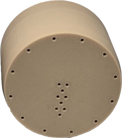
- v0.4
-
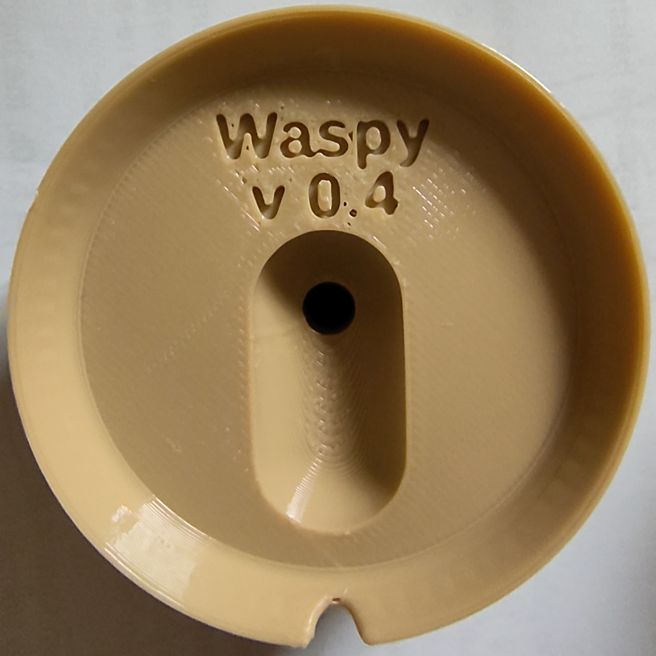
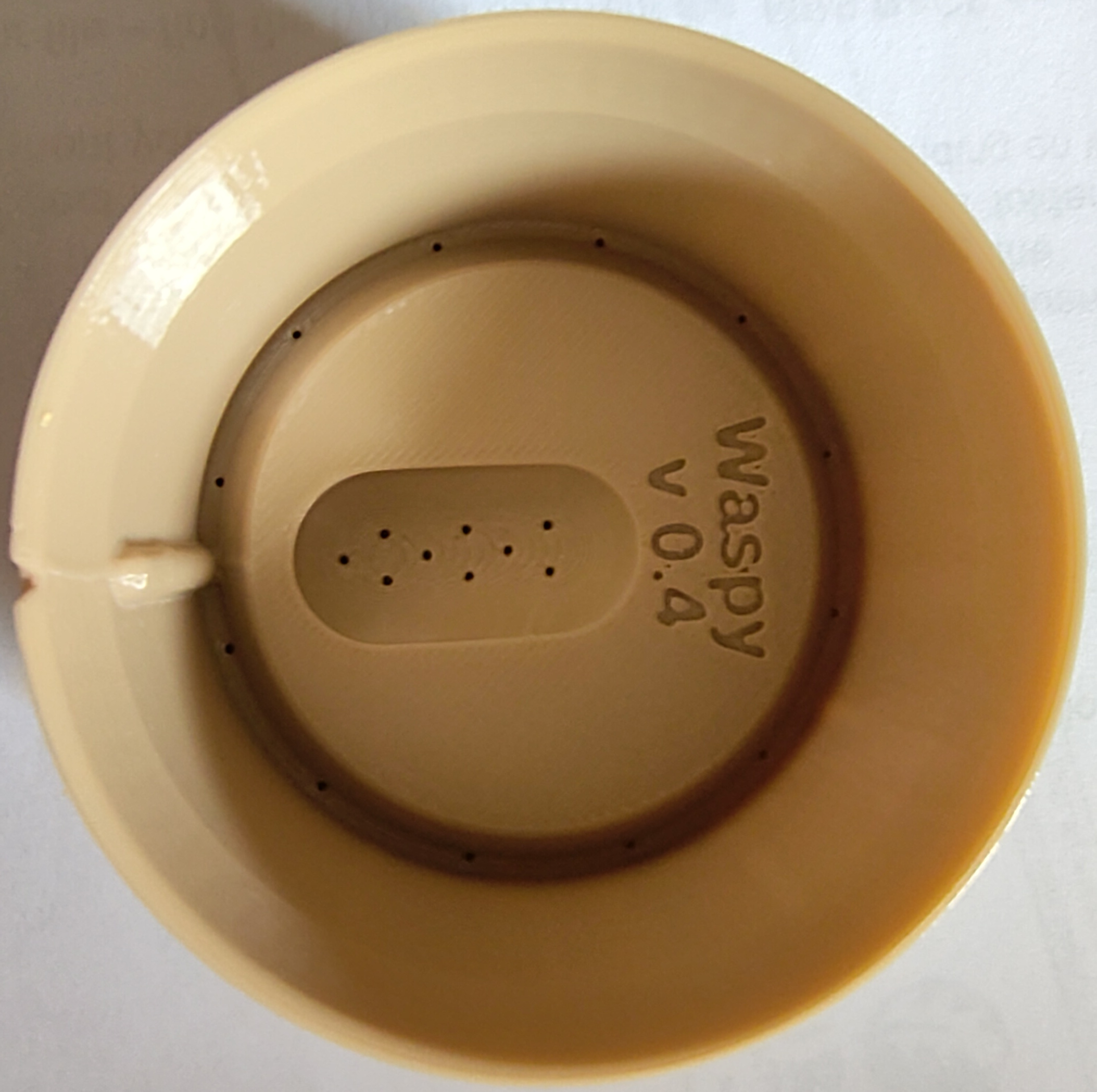
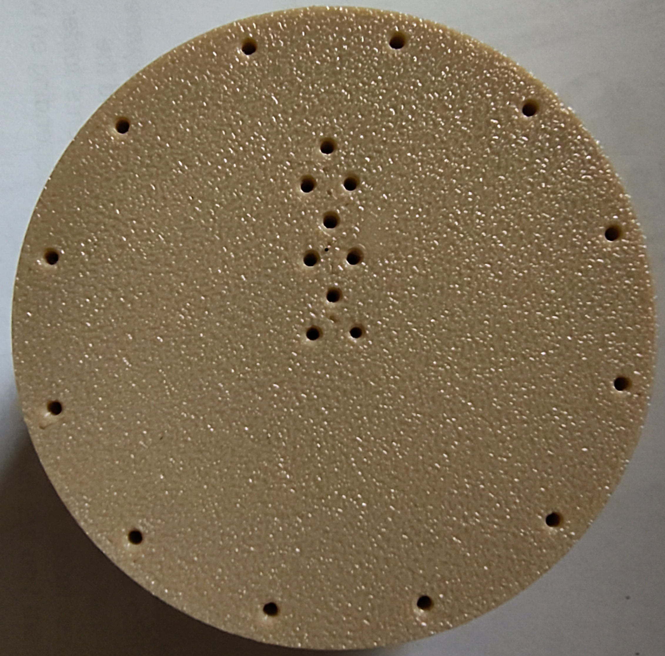
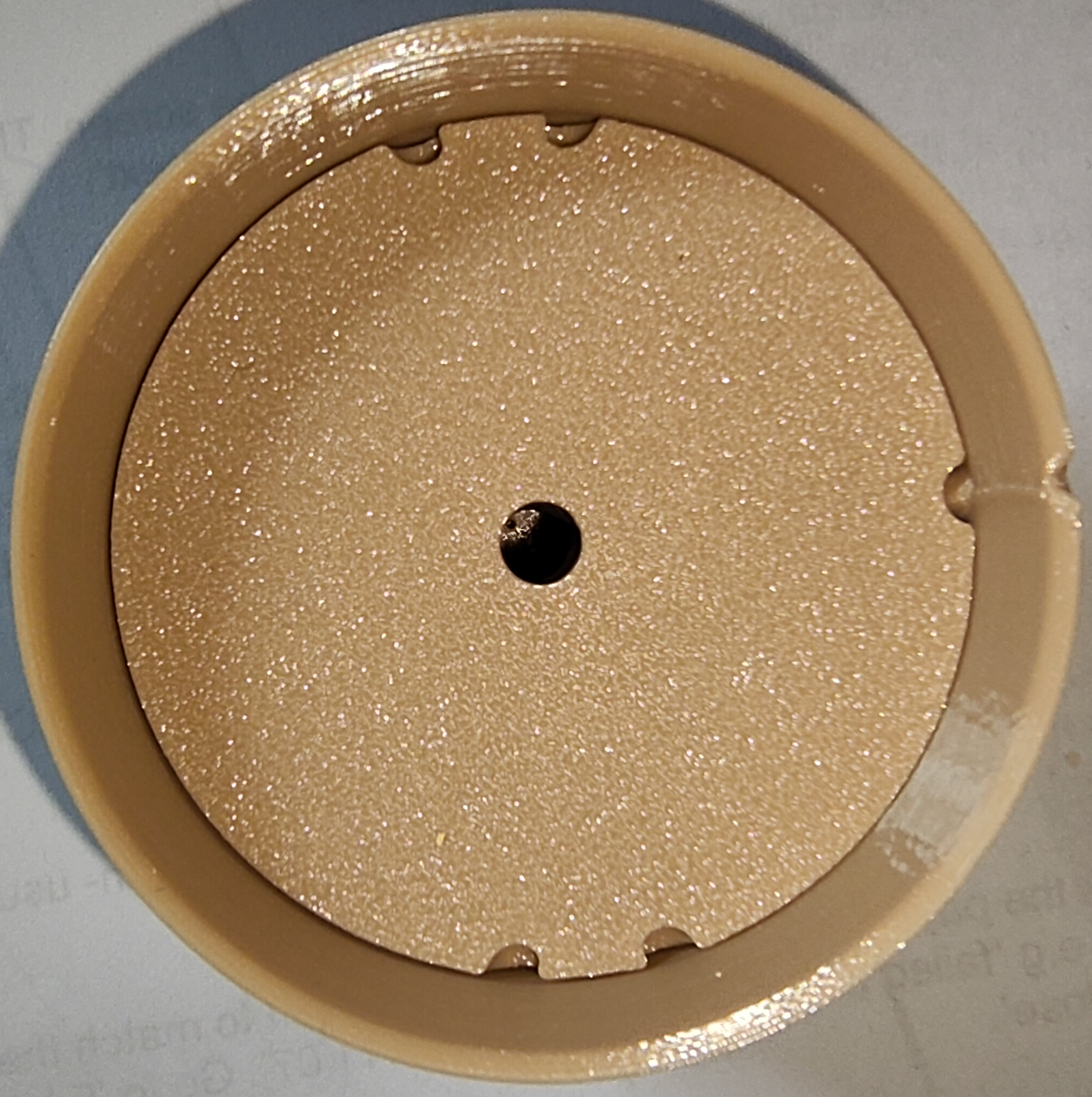
Printed in light brown PETG, using 60% infill & a standard 0.2 mm nozzle, using FFF, by "Temprint".
Observations
-
The cap fits precisely into the base; the build-quality is exceptional. The two parts still rattle when shaken radially, but one couldn't reliably achieve a closer fit with this process.
-
The toroidal channel has been acceptably well formed. Since the entrance-hole is on the perimeter, half of it is missing leaving a semi-circle, so the Nylon thread must be thin enough to enter this restricted channel.
Perhaps the radius of the channel could be slightly increased.
-
The vertical key inside the base seems to have left an echo on the inner & outer surfaces of the tube, but there's no obvious consequence.
-
All the drainage-holes have been well formed.
Mesh Downloads -